
Home / Products / Overhead power line masts / Power Line Pole Types by Purpose: Suspension, Tension, Angle, Terminal
Overhead power line masts
Power Line Pole Types by Purpose: Suspension, Tension, Angle, Terminal
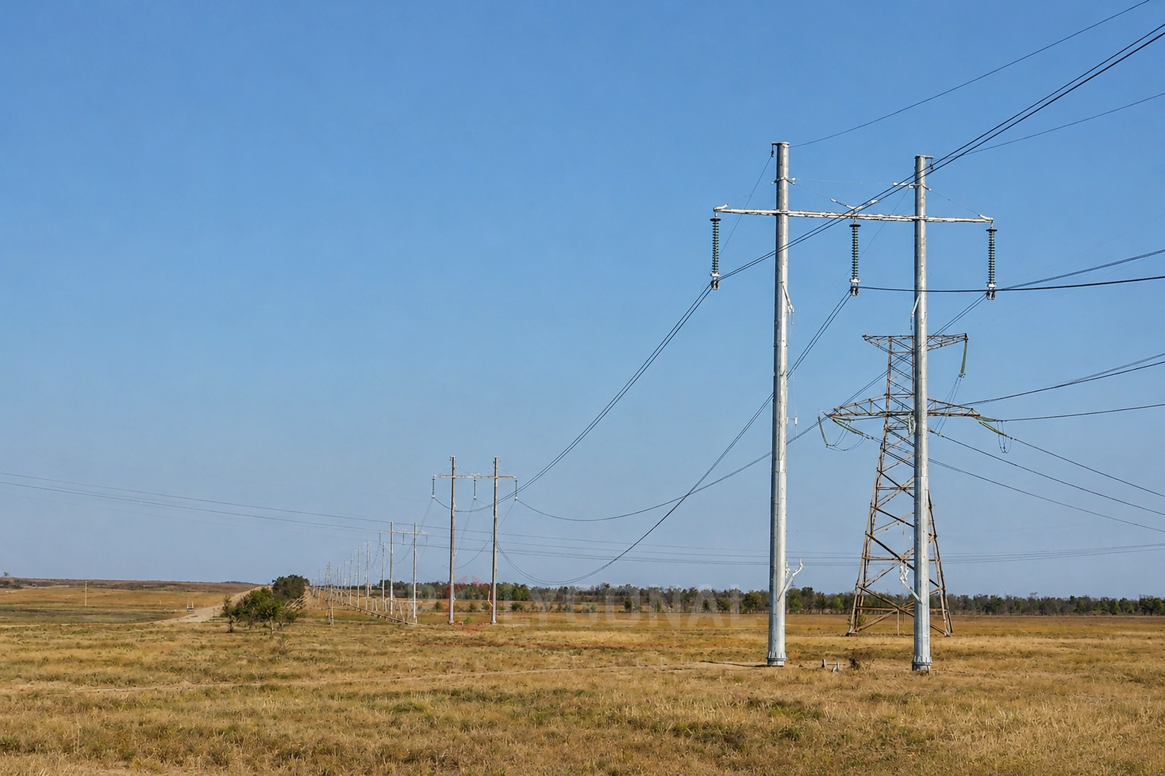
Power line poles differ not only by voltage and material, but also by their role in the route. The pole type determines the load it carries, and so its design.
Contents
- Suspension poles
- Tension poles
- Angle poles
- Terminal (dead-end) poles
- Transposition poles
- Normal and light tension poles, transposition, crossing poles
- Comparing pole types
- Classification by other criteria
- Why the pole type matters for the calculation
- How pole types are placed along the route
- Example: pole layout on a 10 km route
- What to state in the request and which mistakes to avoid
Suspension poles
Suspension (intermediate) poles stand on straight sections of the route and only support the wires and cables through insulator strings or clamps — they do not take the longitudinal tension of the wires, only the wire weight and the wind load across the route. This is the most common type: 80–90% of all poles on a line are suspension poles, so reducing structure weight matters most for them.
Tension poles
Tension (anchor) poles rigidly fix the wires (with tension strings or clamps) and take the difference in wire tension on both sides — so they are designed for a much greater longitudinal load than suspension poles and are built structurally stronger. Tension poles are usually placed at crossings of structures, roads, rivers and other obstacles, and wherever the wire grade, cross-section or number changes — at these points the line must hold even if a wire breaks on one side.
Angle poles
Angle poles stand at turning points of the route and take the resultant force from the change in wire direction. Depending on the turning angle:
- suspension angle poles — for small turning angles, 15–30°: structurally closer to suspension poles, reinforced for the side load;
- tension angle poles — for turning angles above 30°: designed as tension poles, since the load from the turn approaches the load from a one-sided wire break.
Terminal (dead-end) poles
Terminal poles stand at the very start and end of the line, where it connects to a substation switchyard or another facility. Like tension poles, they take the one-sided tension of all wires and cables, so their design is similar to tension poles.
Transposition poles
On long high-voltage lines the phase wires are periodically swapped (transposed) to equalise the mutual inductance and capacitance between phases and reduce voltage asymmetry. The pole where this phase reconnection is carried out is called a transposition pole — structurally a type of tension pole with extra cross-arms for the reconnection scheme. We design such poles individually for the specific transposition scheme.
Normal and light tension poles, transposition, crossing poles
Under the Rules for the Arrangement of Electrical Installations (PUE), 2026 edition, cl. 2.5.80 and 2.5.134, tension poles are either normal or light in design, depending on the failure case they are calculated for. For aluminium wires and PS and PMS steel wires of any cross-section, and for steel-aluminium and aluminium-alloy wires up to 150 mm², a normal pole is calculated for the break of two phases in one span, a light pole for one phase. For steel-aluminium and heat-treated aluminium-alloy wires of 185 mm² and above, a normal pole is calculated for the break of one phase. Separately, a tension pole is calculated for the break of one earth wire.
Under PUE (2026 edition), cl. 2.5.8, on lines of 110 kV and above longer than 100 km one full cycle of phase transposition is required to limit current and voltage asymmetry. Incomplete cycles, segments of different lengths and more cycles are permitted if the calculated asymmetry stays within 0.5% for voltage and 2% for negative-sequence current.
Under PUE (2026 edition), the requirements for poles that limit a crossing span depend on what the line crosses; the designer takes the final values from the current text of the PUE.
| What the line crosses | Poles that limit the crossing span |
|---|---|
| General-use railway, electrified or due to be electrified | Must be normal-design tension poles; on sections with especially heavy and heavy train traffic, metal ones (cl. 2.5.210) |
| Road of category IA or IB | Must be normal-design tension poles (cl. 2.5.215) |
| Road of categories II–V | May be light-design tension poles or suspension poles (cl. 2.5.215) |
Comparing pole types
| Pole type | Load | Typical position on the route |
|---|---|---|
| Suspension | Wire weight and cross-wind only | Straight sections (80–90% of poles) |
| Tension | Difference in wire tension on both sides | Crossings of obstacles, wire grade change |
| Suspension angle | Side load from a 15–30° turn | Gentle route turns |
| Tension angle | Close to a tension pole’s load | Turns above 30° |
| Terminal | One-sided tension of all wires | Start and end of the line, at a substation |
| Transposition | As a tension pole, plus extra cross-arms | Phase-swap points on long lines |
Classification by other criteria
Besides purpose, power line poles are classified by other, independent criteria: by material (wood, reinforced concrete, steel multi-sided and lattice — compared in Transmission Poles: Multi-Sided, Lattice or Reinforced Concrete) and by circuit count (single-circuit and double-circuit — see Double-Circuit Power Line Poles).
Why the pole type matters for the calculation
Pole type and purpose are among the main inputs for design: tension, tension-angle and terminal poles withstand much greater loads than suspension poles, so they come out heavier and more expensive than suspension poles of the same height. Specifying the correct type in the technical specification gives an accurate calculation instead of a margin added “just in case”.
Pole height also depends on the line’s voltage class: the ranges for each class 35–750 kV are in the article Transmission Pole Height by Voltage Class.
How pole types are placed along the route
The type of each pole is set from the route plan and profile, not by guesswork. The sequence is roughly this:
- terminal poles go at the start and end of the line; where an overhead line changes over to a cable, a terminal pole or a transition point is used (PO-KV for 35–110 kV lines);
- every noticeable turning point gets an angle pole: a suspension angle pole for moderate angles (15–30°), a tension angle pole for angles above 30°; a very slight change of direction, a few degrees, can also be taken by an ordinary suspension pole, which the calculation confirms;
- crossings of roads, rivers and other lines, and places where the wire grade or cross-section changes, usually get tension poles; the final choice of type rests with the crossing design;
- the remaining straight sections between these points are filled with suspension poles.
Tension poles also divide the line into tension sections and limit how far a failure spreads: after a wire breaks, the difference in tension is taken by a tension pole, not by a chain of suspension poles. Under PUE (2026 edition), cl. 2.5.135, on lines above 1 kV the distance between tension poles must not exceed: 3 km on lines up to 20 kV with suspension insulators (including 6–10 kV lines with such insulators, see 6–10 kV poles); 1.5 km (ice regions 1–3) or 1 km (regions 4 and above) on lines up to 35 kV with pin insulators; 10 km on new lines of 35 kV and above with suspended conductors, or 5 km in hard-to-reach terrain and in especially difficult natural conditions.
Example: pole layout on a 10 km route
Assumed data, not a real project: a 10 km route, spans of 250 m, turns of 20°, 25° and 45°, and one road crossing on two tension poles (one on each side). That gives 10,000 ÷ 250 = 40 spans, so 41 poles.
The 250 m span is an assumption; on 6–10 kV lines spans are shorter, so there would be more poles. The 45° angle does not exceed what our tension angle poles for 110 kV allow.
| Pole type | Where it stands | Count |
|---|---|---|
| Terminal | Start and end of the line | 2 |
| Suspension angle | Turns of 20° and 25° | 2 |
| Tension angle | Turn of 45° | 1 |
| Tension | Road crossing, both sides | 2 |
| Suspension | Straight sections between the key poles | 34 |
| Total | 40 spans + 1 | 41 |
Check: 2 + 2 + 1 + 2 + 34 = 41. Suspension poles: 34 ÷ 41 ≈ 83%, within the typical 80–90%. The example is simplified: the real layout comes from the route design.
What to state in the request and which mistakes to avoid
In the request, state the lengths of adjacent spans, the grade and cross-section of the wires and earth wire, and the wind and ice regions (loads on power line poles); for key poles, also the turning angle in degrees at each point and why a tension pole is needed there. The most common mistakes:
- ordering only suspension poles without singling out the key poles: there are few of them, but they carry more load;
- not stating the turning angles: with 30° as the dividing line, poles for 28° and 33° belong to different types, so refining the route can change the type and cost; the maximum permitted angle also depends on the pole series;
- not allowing for heavier wires later: a pole is designed for specific wires, so switching to heavier wire means recalculation.
Updated:
Power line pole types: frequently asked questions
Which pole type is most common on a line?
Suspension — 80–90% of all poles on a line. Tension, angle and terminal poles stand at fewer, key points of the route but carry much greater loads.
How is a tension pole different from a suspension pole?
A tension pole rigidly fixes the wires and takes the difference in tension on both sides (including if a wire breaks on one side), so it is structurally stronger. A suspension pole only supports the wires and is not designed for such loads.
What is a transposition pole?
A pole where the phase wires are swapped (transposed) to equalise the electrical parameters of a long line. Structurally a type of tension pole with extra cross-arms; we design it individually for the transposition scheme.
Does the pole type affect the price?
Yes. Tension, tension-angle and terminal poles carry greater loads and so are heavier and more expensive than suspension poles of the same height and voltage class.
How many angle poles does a route need?
Usually one at each turning point where the angle calls for it. The number depends on the route plan, not on the line length; the turning angle decides whether it is a suspension or a tension pole.
Can a suspension pole be used at a road crossing?
Sometimes it can, depending on what the route crosses. Under PUE (2026 edition), cl. 2.5.215, on roads of categories II–V the poles that limit the crossing span may be light-design tension poles or suspension poles, while on roads IA and IB they must be normal-design tension poles; so too on general-use railways, electrified ones and those due to be electrified (cl. 2.5.210). For 6–10 kV lines we design transition poles of both tension and suspension type. At critical crossings (major roads, railways, rivers) tension poles are the usual choice: they limit the effects of a wire break. The final choice of type rests with the crossing design.
Related products: Overhead power line masts · Overhead line fittings and crossarms (0.4-10 kV)
More on this topic: Typical Lattice Power Line Poles: Classification and Checks · Typical Lattice Transmission Poles 35–750 kV · Steel Multi-sided Poles for 6–10 kV Lines · Power Line Protection Zone: Widths by Voltage Class · Distance Between Power Line Poles: What Determines the Span Length · Steel Multi-sided Poles for 35 kV Lines
Get a quote for your requirements
Send us your requirements — we will calculate the price and lead time.