
Home / Products / Overhead power line masts / Double-circuit Transmission Poles: What They Are and When to Use Them
Overhead power line masts
Double-circuit Transmission Poles: What They Are and When to Use Them
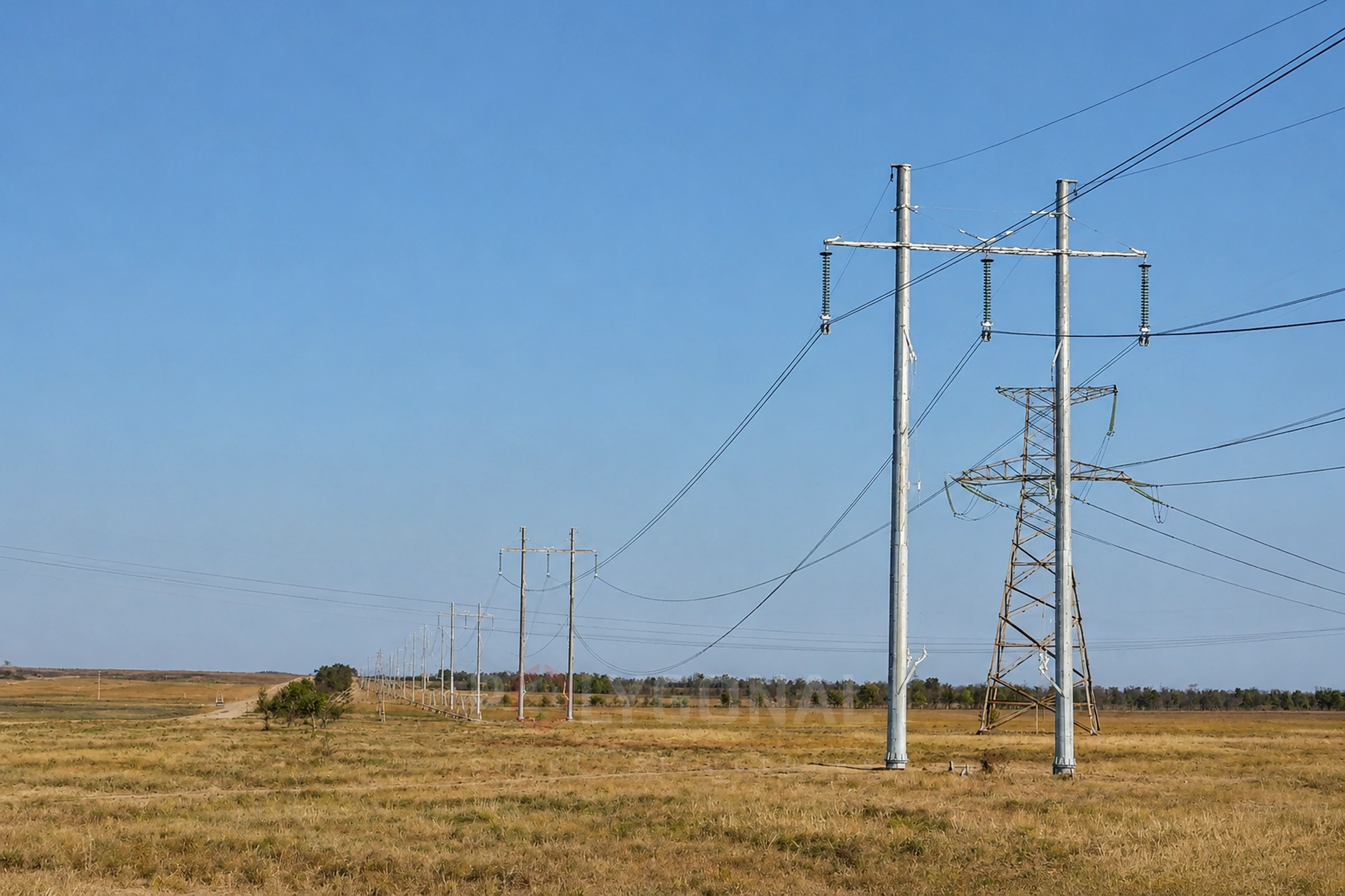
A double-circuit pole carries two independent electrical circuits on one structure instead of two separate lines. We explain why this is done and which double-circuit poles we manufacture.
Contents
- What a double-circuit pole is
- Why double-circuit poles are used
- Double-circuit poles in our range
- One double-circuit line or two single-circuit lines
- Example: a 3 km 110 kV line
- What to include in a request for a double-circuit pole
- Common ordering mistakes
- What the codes say about these poles
- Distance between the circuits on one pole
- What the PUE says specifically about double-circuit poles
- Crossings and reliability class
What a double-circuit pole is
A single-circuit pole carries one three-phase circuit (three phase conductors, sometimes with an earth wire). A double-circuit pole carries two independent three-phase circuits on one structure — usually in two tiers of cross-arms, one circuit per tier.
Why double-circuit poles are used
- saving the right-of-way: one double-circuit pole takes up less land for the route than two single-circuit poles — important where the corridor width is limited (built-up areas, other utilities, difficult terrain);
- supply from two independent sources, or along two routes to the same facility over a shared corridor;
- supply redundancy: if one circuit is switched off (a fault or planned outage), the other keeps supplying power. This redundancy is at the electrical-circuit level only — mechanical damage to the pole itself (for example, icing or a storm) affects both circuits at once, so a double-circuit pole does not fully replace two physically separate, independent routes.
Double-circuit poles in our range
We make double-circuit intermediate multi-sided poles for 35 kV (conductors up to AC 120/27) and 110 kV (conductors up to AC 240/32, with a raised double-circuit intermediate version also available for greater ground clearance). At 35 kV we also make double-circuit end and angle-anchor (up to 79°) poles, while at 110 kV only the intermediate poles are double-circuit. A double-circuit version is also provided for PO-KV cable-overhead transition points at 35–110 kV.
Double-circuit solutions also exist among typical lattice poles — by purpose (intermediate, anchor, angle) they are further divided by number of circuits: single-, double- and multi-circuit. See Typical Unified Lattice Transmission Poles.
For 6–10 kV distribution lines we do not offer double-circuit solutions — at this voltage class, wood or reinforced-concrete poles with separate circuits are mostly used.
One double-circuit line or two single-circuit lines
Compare the two options on four criteria.
| Criterion | Two single-circuit lines | One double-circuit line |
|---|---|---|
| Poles at each point of the route | Two separate poles, each with its own fixing in the ground | One pole (at 35 kV, made with three shafts) |
| Land strip | Two strips (the protection zones may overlap), wider in total | One strip, narrower |
| Phase conductors per pole | 3 | 6: twice the wind load from the conductors |
| Repairing one circuit | The lines are set apart, so the neighbouring line has less effect; induced voltage from a parallel line is still taken into account | If the other circuit stays live: extra safety measures because of induced voltage |
The final choice depends on the route and the project input data.
Example: a 3 km 110 kV line
Assumed data: span 200 m, 8 m between the outermost conductors, 30 m between the axes of two single-circuit lines. The 110 kV protection zone extends 20 m on each side from the projection of the outermost conductors (dimensions by voltage class).
| Item | Two single-circuit lines | One double-circuit line |
|---|---|---|
| Poles along the route | 32 | 16 |
| Strip width including protection zones, m | 78 | 48 |
Calculation: 3,000 ÷ 200 = 15 spans, so 16 poles; 2 × 16 = 32. Strip: 8 + 2 × 20 = 48 m; (30 + 8) + 2 × 20 = 78 m. The difference is 30 m: the strip is 38% narrower (30 ÷ 78). The example is simplified: all poles are treated as the same type, and anchor and angle points are not singled out. There are half as many poles, but each is heavier; the real figures come from the project.
What to include in a request for a double-circuit pole
- voltage class and pole type: intermediate, anchor, angle or end (see Power Line Pole Types by Purpose);
- conductor type and cross-section of each circuit: our double-circuit intermediate poles are designed for conductors up to AC 120/27 at 35 kV and up to AC 240/32 at 110 kV;
- whether both circuits are strung at once: if the second comes later, the pole is designed for both from the start;
- route angle: a double-circuit 35 kV angle-anchor pole allows up to 79°; at 110 kV the anchor and angle-anchor poles (up to 45°) are single-circuit, so agree the anchor points of a double-circuit 110 kV route separately;
- wind and ice regions, soils, and the fixing method: a drilled pit 3.0 m deep (35 kV) or 4.0 m deep (110 kV), or a flange (for design cases, see Loads on Overhead Lines).
Common ordering mistakes
- designing the pole for the first circuit only and stringing the second later without a recalculation;
- comparing only the number of poles: there are fewer, but each is heavier, and the pole and its fixing in the ground take the load of six conductors;
- ordering intermediate poles only, without thinking through the anchor and angle points of the route;
- not stating different conductor cross-sections of the two circuits when they differ.
What the codes say about these poles
The rules below come from the Rules for the Arrangement of Electrical Installations (PUE), 2026 edition; the final figures for a site come from the design.
For lines up to 330 kV the PUE recommends free-standing double-circuit and multi-circuit poles on cultivated land, in built-up areas and in cramped conditions on the approaches to power stations and substations. Guyed poles are not allowed on cultivated land unless the guys are protected from farm machinery.
Distance between the circuits on one pole
The two circuits cannot be brought together at will: the PUE sets a minimum distance between the nearest conductors of different circuits, and it grows with voltage. For 35 kV the values are for suspension insulators.
| Voltage class, kV | Minimum distance between the nearest conductors of different circuits, m |
|---|---|
| 35 | 3 |
| 110 | 4 |
| 150 | 5 |
| 220 | 6 |
| 330 | 7 |
| 500 | 8.5 |
PUE (2026 edition), cl. 2.5.101. For 35 kV lines with post insulators the minimum is 2.5 m. The final distance comes from the design, with conductor clearance within the span taken into account. We make double-circuit poles for 35 and 110 kV.
What the PUE says specifically about double-circuit poles
Besides the distance between the circuits, the PUE (2026 edition) has several more provisions for double-circuit and multi-circuit lines: some are requirements, others only recommendations or permissions.
- design: the poles of such lines must also be designed, in every mode, for the case when only one circuit is mounted (cl. 2.5.77);
- phase order: on double-circuit lines of 110 kV and above, opposite phase order in the two circuits is recommended (cl. 2.5.8);
- insulators: on such lines, whatever the voltage, glass or polymer suspension insulators are required (cl. 2.5.104);
- earth wire: on such 35 kV lines a steel earth wire is, as a rule, taken with a cross-section of at least 50 mm²; if the earth wire is steel-aluminium (or aluminium alloy with a steel core), the sum of the cross-sections of its aluminium (alloy) and steel parts must be at least 120 mm² at any voltage (cl. 2.5.88);
- lightning flashovers: on lines of 110 kV and above that are protected by an earth wire, the insulation of one circuit may be made 20–30% stronger than that of the other circuit, to reduce the number of flashovers between the circuits (cl. 2.5.126);
- earthing: whatever the pole height, it is recommended to halve the earthing resistance compared with the value in Table 2.5.29 (cl. 2.5.127).
Crossings and reliability class
The PUE requires a crossing of a 35–500 kV line with a double-circuit line of the same voltage, one that supplies consumers with no backup or whose circuits back each other up, to be made, as a rule, in different spans separated by an anchor pole.
For a double-circuit line whose circuits back each other up (or that supplies consumers with no other backup) the PUE allows, in justified cases, ice and ice-and-wind loads one reliability class higher; this applies to 6–330 kV lines. The design decides which class to use; for design loads see Loads on Overhead Lines.
Updated:
Double-circuit poles: frequently asked questions
How does a double-circuit pole differ from a single-circuit one?
A double-circuit pole carries two independent three-phase circuits on one structure (usually in two tiers of cross-arms); a single-circuit pole carries only one.
Is a double-circuit pole always more expensive than a single-circuit one?
Yes, it is heavier and more massive (two circuits of conductors and double cross-arms), but one double-circuit pole replaces two single-circuit poles and takes up less land for the route — so the overall cost of the line can be lower.
Can a double-circuit pole be considered a backup power supply?
Yes, but only at the electrical-circuit level: if one circuit is switched off, the other keeps working. Both circuits are equally exposed to damage to the pole itself (for example, icing or a storm).
Which double-circuit poles do you manufacture?
Double-circuit multi-sided poles: at 35 kV, intermediate (up to AC 120/27), end and angle-anchor (up to 79°); at 110 kV, intermediate (up to AC 240/32, including a raised version). Also a double-circuit version of the PO-KV transition points.
How many conductors does a double-circuit pole carry?
Six phase conductors, three per circuit (2 × 3 = 6), plus an earth wire if needed. So the wind and vertical load from the conductors on the pole is twice that on a single-circuit pole for the same span.
Can the second circuit be strung later?
Yes, if the pole was designed for two circuits from the start. State this in the technical specification: a pole designed for one circuit must not be loaded with a second one without a recalculation.
How many shafts does a double-circuit pole have?
At 35 kV the double-circuit end, angle-anchor and intermediate poles are made with three shafts, fixed in a drilled pit 3.0 m deep or by flanges. A single-shaft pole can be designed for special conditions; the option is agreed on the basis of the project input data.
What is the minimum distance between the circuits on a double-circuit pole?
Under the PUE (2026 edition), cl. 2.5.101, the distance between the nearest conductors of different circuits must be at least 3 m at 35 kV (suspension insulators) and 4 m at 110 kV. This is a minimum: the final distance comes from the design.
How are the two circuits told apart on one pole?
Where a pole carries the dispatch name of the line, a double-circuit pole also shows the circuit. The PUE (2026 edition), cl. 2.5.18, requires this.
Related products: Overhead power line masts
More on this topic: Typical Lattice Power Line Poles: Classification and Checks · Typical Lattice Transmission Poles 35–750 kV · Steel Multi-sided Poles for 6–10 kV Lines · Power Line Pole Types by Purpose: Suspension, Tension, Angle, Terminal · Power Line Protection Zone: Widths by Voltage Class · Distance Between Power Line Poles: What Determines the Span Length
Get a quote for your requirements
Send us your requirements — we will calculate the price and lead time.