
Home / For Designers / Loads on Power Line Poles: Wind and Ice
Knowledge base
Loads on Power Line Poles: Wind and Ice
Transmission line poles work together with the conductors and earth wires as a single system. Here is what loads set the size of poles and foundations, how wind, ice and temperature act, and the cases overhead lines are designed for.
Contents
Line poles: taking the specifics of a line into account
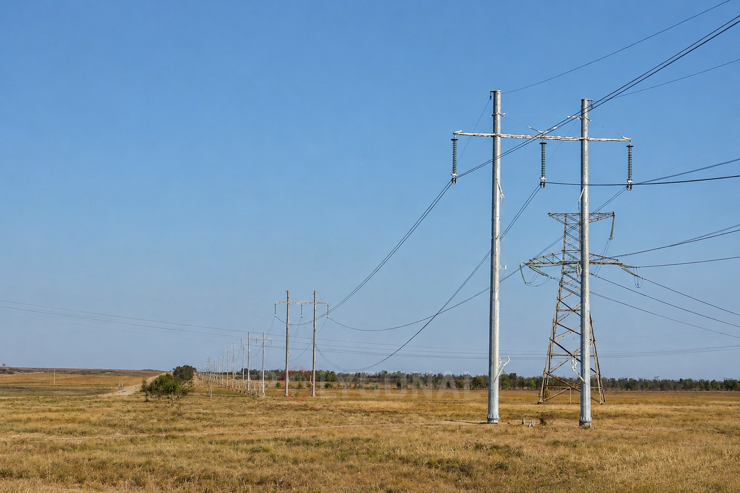
A high-voltage line is a complex structural system. Under load it acts as a three-dimensional net: the poles are joined by conductors and earth wires.
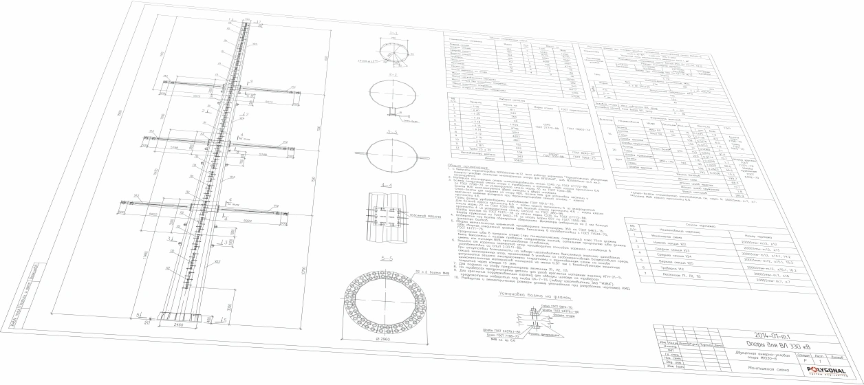
In Ukraine high-voltage lines are still built mostly from typical unified poles. Each is designed for a range of parameters, and on flat terrain that range is wide. The price is extra metal: the nearest larger structure from the catalogue is taken instead of the one needed, and the pole height and spacing are fitted to the terrain by changing the span and adding standard shaft sections, which needlessly strengthens the chords, lattice and cross-arms. Lately polygonal poles designed for a particular line have become widespread.
Reserves of load capacity in a line in service can be obtained by:
- taking into account the actual wind, ice and temperature loads in the area of the line;
- refining the loads from equipment: conductors, earth wires, insulators and fittings;
- refining the permanent loads from the self-weight of the steel structures, which matters especially for crossing poles;
- using more modern methods of determining loads and calculating structures.
By direction, loads on a line are horizontal or vertical. The size of pole members and foundations is set mainly by horizontal loads: hurricane wind, wind combined with ice, and broken conductors and earth wires. In this poles differ sharply from many other structures, whose size is set mainly by permanent self-weight and useful loads.
The following loads are taken into account when calculating poles.
Horizontal:
- wind load on the pole structure;
- wind load on conductors and earth wires;
- load from the tension of conductors and earth wires.
Vertical:
- self-weight of the pole;
- weight of insulator strings with fittings;
- weight of conductors and earth wires, with and without ice.
Overhead line loads
Atmospheric loads and effects
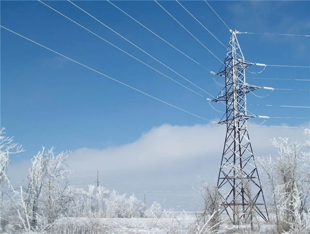
Conductors and earth wires work in harsh conditions: wind, ice, chemically active impurities in the air and vibration act on them. Large mechanical stresses arise in the conductor material. Operating conditions of a line depend largely on the climate of the area: temperature, wind, humidity, icing conditions and types of deposit (glaze, rime), and thunderstorm activity. So climatic conditions must underlie any assessment of the technical condition of a line.
The climate of an area is established by statistical processing of many years of meteorological observations. Sometimes one has to make do with data for a relatively short period, and the results cannot always be extended to sections between weather stations, especially in mountains. If a section may see harsher climatic conditions than the surrounding area, special observations and information from power utilities and other bodies are needed.
Wind load
Wind pressure has a steady part, set by the mean flow speed, and a variable part caused by gusts. The dynamic effect of gusts grows with the natural period of the structure. The Rules for the Arrangement of Electrical Installations (PUE), 2026 edition, take it into account with a dynamic coefficient Cd: for poles up to 50 m high it may be taken by pole type (1.5 for a free-standing single-shaft steel pole), and for poles above 50 m it comes from a special dynamic calculation to DBN V.1.2-2 (cl. 2.5.42). For conductors and earth wires the dynamics are counted too, with a coefficient Cdc that depends on the terrain type, the wind pressure and the span length: the longer the span, the smaller it is, because gusts on different parts of a span do not peak at the same time (cl. 2.5.49–2.5.50).
For poles the horizontal component of the wind matters most. Wind presses on conductors, earth wires and poles and, by loading the conductors sideways, raises their tension. Excessive wind load can break and topple poles, sometimes pulling out foundations that are not firmly enough anchored in the soil.
The mechanical strength of poles and conductors is checked for the maximum wind pressure. The PUE give it not as a speed but as a pressure: the territorial zoning map has five regions, from 400 to 600 Pa at a height of 10 m on plain terrain (mean return period 50 years, cl. 2.5.27 and 2.5.41); for lines of reliability class 3 or 4 (110–330 and 500–750 kV) the pressure should be taken from regional maps (cl. 2.5.29). The wind load can be refined by refining the wind speed (cl. 2.5.30). In practice, using local meteorological data usually lets the load be reduced compared with the map value. This requires choosing the right weather station and allowing for the real measurement conditions; such questions should be settled by specialists in applied climatology, and the source data on wind should be obtained from the relevant state meteorological bodies.
Ice, rime and wet snow
Icing deposits (glaze ice, granular rime, their mixture and wet snow) considerably increase the weight and wind area of conductors. The characteristic ice load is normalised to a conductor 10 mm in diameter at a height of 10 m above the ground on plain terrain, with a mean return period of 50 years (cl. 2.5.27, 2.5.35). The types of deposit, their thickness and density are described in Ice, Rime and Wet Snow on Power Lines.
Temperature and climate effects
Air temperature directly affects the tension and sag of conductors and earth wires.
The change of temperature over a day is called the daily cycle and over a year the annual cycle. Climatological temperature maps compiled from many years of data can be used to find extreme values: the PUE take the mean annual, lowest and highest temperatures from maps (cl. 2.5.58–2.5.60) and use −5 °C during icing (cl. 2.5.61).
Design cases of overhead lines
Under PUE (2026 edition), Table 2.5.14, the calculation for normal operation (conductors and earth wires intact) is made for these combinations of climatic conditions:
- mean annual temperature, no wind or ice;
- highest temperature, no wind or ice (for conductors and earth wires only);
- lowest temperature, no wind or ice;
- ice at its design value, temperature −5 °C, no wind;
- maximum wind pressure, temperature −5 °C, no ice;
- wind during icing, temperature −5 °C, ice at 0.9 of its design value.
Wind and ice are taken from the PUE maps (cl. 2.5.29, 2.5.35, 2.5.41); the values read from the maps, ice included, may be refined with long-term observations (cl. 2.5.30). The designer takes the final values for a particular line from the current text of the PUE.
By Table 2.5.14, the emergency-condition calculation is made for three combinations: mean annual temperature with no wind or ice; lowest temperature with no wind or ice; ice at its design value at a temperature of −5 °C with no wind.
Poles are also checked separately for erection conditions (Table 2.5.14: temperature −15 °C, wind pressure 62.5 Pa at a height of 10 m, no ice) and for the approach of live parts to pole members and structures (cl. 2.5.85): at working voltage with the design wind pressure, −5 °C and no ice, and under lightning and internal overvoltages at +15 °C with wind at 0.1 of the design pressure but not less than 62.5 Pa, or with no wind.
Reliability classes of overhead lines: how voltage sets the return period
PUE (2026 edition), cl. 2.5.26, Tables 2.5.1 and 2.5.2, divide lines into four reliability classes by voltage. The higher the class, the longer the mean return period of the design loads.
| Class | Voltage, kV | Return period, conductors and earth wires, years | Return period, poles and foundations (strength), years |
|---|---|---|---|
| Class 1 | up to 1 | 5 | 30 |
| Class 2 | 1–35 | 10 | 50 |
| Class 3 | 110–330 | 15 | 150 |
| Class 4 | 500–750 | 25 | 500 |
Reliability factor for importance γn (building structures): 0.95 for class 1, 1.0 for classes 2 and 3, 1.05 for class 4.
When a class may be raised
In justified cases the ice and wind-with-ice loads for lines of 6–330 kV may be taken one class higher (cl. 2.5.26). The main criteria: icing-and-wind failures on the line exceed the regional average; several lines supplying separate regions or large consumers run in one corridor; a double-circuit line whose circuits back each other up, or a line supplying consumers with no other reserve supply; a multi-circuit line (more than two circuits) of different voltages on shared poles.
Calculation methods
Under cl. 2.5.25 of the PUE, the mechanical calculation of conductors and earth wires is made by the allowable-stress method, and of insulators and fittings by the breaking-load method; both use design values of variable loads with the return periods of Table 2.5.1 (5, 10, 15 or 25 years depending on the reliability class). Poles and foundations are designed by the limit-state method. Any other method must be justified in the project in each case.
What this means for a project
Refining the real loads and taking the specifics of the line into account lets you avoid paying for extra steel in new poles and find reserves of load capacity in existing ones. POLYGONAL carries out verification calculations of typical poles, designs polygonal poles for a particular line and prepares KM and KMD drawings; see the sections on the design of transmission poles and foundations and on calculations of steel structures.
Loads and the cost of a pole
The loads determine the shaft section and the mass of the pole, and so its cost. What else the price of a power line pole depends on, and what it is by voltage class, is on the page Power line pole prices.
Updated:
Reviewed by: V.V. Padalka, Chief Project Engineer
Loads on power line poles: frequently asked questions
When is the dynamic (pulsating) wind component taken into account?
For poles, through the dynamic coefficient Cd: up to 50 m high it may be taken by pole type, above 50 m a special dynamic calculation is needed (cl. 2.5.42). For conductors and earth wires the dynamics are also counted, with a coefficient Cdc (cl. 2.5.49–2.5.50).
Related products: Overhead power line masts · Steel structure design (structural and detail drawings)
Read also: Installation of Multi-sided Poles and Masts · Solar Street Lighting · Power Line Pole Types by Purpose: Suspension, Tension, Angle, Terminal · Cross-arms for 0.4–10 kV Lines: TM and TN Types, Reading the Designation
Get a quote for your requirements
Send us your requirements — we will calculate the price and lead time.