
Home / For Designers / Installation of Multi-sided Poles and Masts
Knowledge base
Installation of Multi-sided Poles and Masts
The procedure for assembling sections, erecting and installing multi-sided lighting and power line poles, floodlight masts, telecom towers and antenna masts: the requirements are the same for all of them.
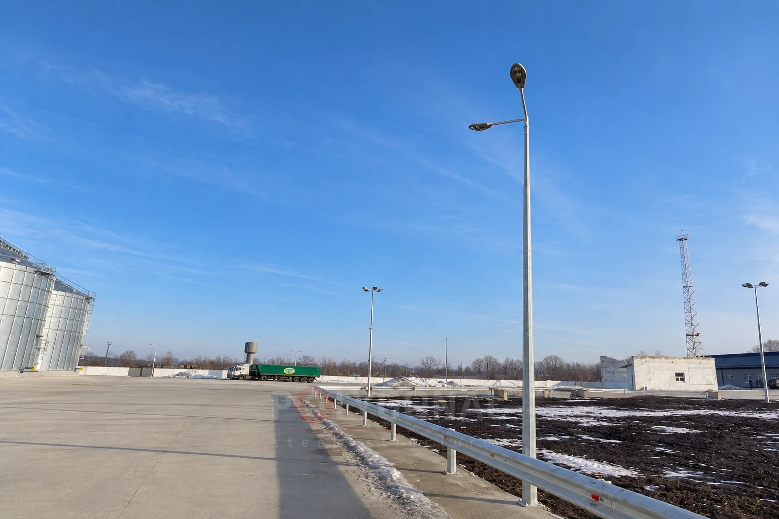
Contents
Assembling lighting poles and floodlight masts
Steel street lighting poles and floodlight masts can consist of one, two or several sections depending on the required height. The maximum section length (shipping element) of a floodlight mast is usually no more than 12 m, determined by how easy it is to transport to the assembly and erection site.
The sections are joined in two ways: with a flanged joint or a slip (telescopic) joint. Assembling a flanged joint on site usually raises no questions, while a slip joint takes some skill.
A slip joint will be reliable and effective if two conditions are met:
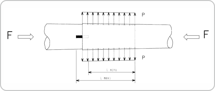
- the length of the slip joint must equal the nominal length within the permitted deviation (given in the design documentation and usually 10–12% of the joint length);
- the sections are pulled together during installation with an increasing load, in steps that depend on the section diameter, until the sections stop moving relative to each other.
Thanks to the taper, the pulling load makes a tight joint between the sections that transmits bending moment without slipping. Such a joint is comparable to a bolted joint with a controlled tightening torque. We recommend a pulling load of at least 10 tonnes. To control the length of the slip joint, manufacturers usually mark the range within which, allowing for the permitted deviation, the sections must lock together. If there is no mark, the erectors make one during assembly according to the assembly instructions or installation diagram that the manufacturer prepares and encloses with the shipping documents.
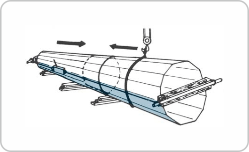
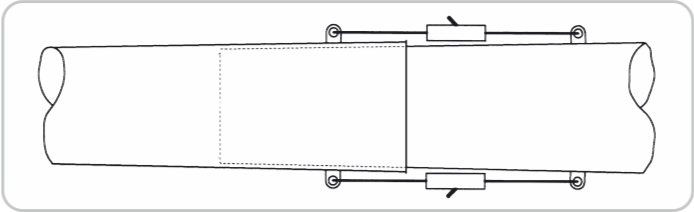
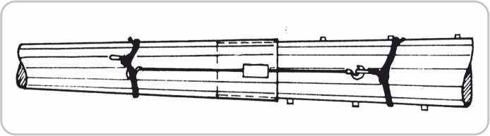
To make assembly easier, the sections are fitted with special lugs to which hand hoists or jacks that create the pulling force are attached. When the sections are pulled together with several jacks or hoists, the load must be applied evenly to avoid skewing and early locking of the sections, which is hard to undo.
If there are no lugs, assembly can be done with a winch: a pulling cable is run inside the sections and attached to the pulling crossbar and the base flange.
During assembly of the sections the following must be done:
- before assembly, make sure the surface in the slip-joint zone is clean and smooth;
- lay the sections one by one on wooden supports that have been levelled beforehand;
- pull the sections together according to the assembly instructions for that pole.
Assembling lighting poles
Erecting lighting poles and floodlight masts
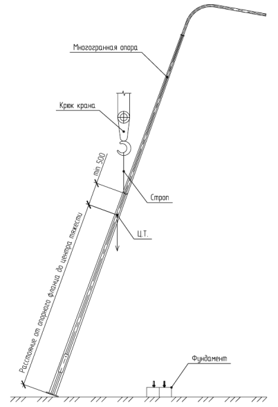
The sections are slung with textile belt slings or steel ropes passed through rubber-fabric sleeves. Bare steel ropes must not be used: they can damage the coating, and a choker hitch can slip during erection.
Once the shaft is assembled, brackets, ladders and service platforms are fitted. After the enlarged assembly the pole can be erected whole or in enlarged parts. The method depends on the design of the mast, the site and the technical equipment of the erection contractor.
Poles and masts must be erected in strict accordance with the work execution plan, which includes process cards and diagrams for individual types of work prepared by specialist organisations. The structures are delivered for erection galvanised (or painted) and cleaned of dirt, ice, oil and rust. Steel structures are inspected on site. Permitted deviations from the design dimensions must meet the technical conditions and the applicable building codes.
The poles can be installed on foundations of various designs depending on the soil conditions given in the geotechnical survey report and the loads from the particular pole.
During erection the following must be done:
- before the pole is placed in the design position, the groundworks (the foundation, levelled as accurately as possible for height and pole axis) must be complete and the foundation must have reached at least 50% strength;
- when lifting, to stop the shaft sections from sliding apart at the slip joints, special slinging methods are used, or the slip joint is fixed at the lugs with temporary devices that are removed after lifting;
- where the sling is attached, the poles must have padding to protect the zinc coating;
- the structure is aligned and all nuts on the base flange are fully tightened before the slings are removed; the slings are removed only after all foundation nuts are fully tightened;
- the erection bolts should be tightened to a torque of at least 15 kgf·m;
- bolt heads and nuts must sit tightly against the surfaces of the structural elements and washers; at least one full-profile thread must remain on the nut side of each bolt;
- the anchor bolt nuts of the foundation are secured by a second nut (lock nut);
- bolt tightening is checked by tapping with a 0.4 kg hammer: the bolt must not tremble or move; tightness of the joint is checked with a feeler gauge;
- to make bolted joints of galvanised structures more reliable, it is recommended to tighten the nuts again a week after the first erection to compensate for zinc creep;
- as the specific project requires, an additional earth connection with an M16 bolt must be attached to the pole contact.
Poles can be erected with cranes of various types of suitable lifting capacity and jib reach, and in hard-to-reach places (mountains, rivers, forest) and dense urban areas with helicopters. During erection, mechanical damage to the structures (permanent deformation, dents, etc.) and to protective coatings is not allowed. Transport and erection loads on the poles must not exceed the design service loads.
Installation procedure
Before the multi-sided poles are placed in the design position, the groundworks (the foundation) must be complete. Before installation begins, the steel structures must be assembled according to the working design documentation and the installation process cards. The process cards are part of the work execution plan prepared by a specialist erection contractor.
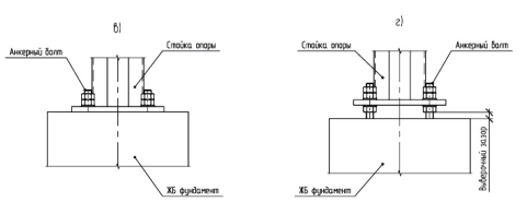
The shaft of a multi-sided pole is fixed to the foundation through a flange. Poles of types “a” and “c” must be erected on foundations that have already been levelled, while for types “b” and “d” levelling is done during erection by adjusting the base nuts.
Poles are slung with textile belt slings or steel ropes passed through rubber-fabric sleeves, using a choker hitch, so that the sling is at least 500 mm above the pole’s centre of gravity. Bare steel ropes must not be used.
Installation procedure:
- lift the pole and place it on the anchor bolts of the foundation;
- fix the shaft to the foundation with nuts;
- finally tighten all fixing nuts in pairs and remove the slings.
During erection you should also:
- place the pole on the foundation according to the site plan;
- remove the slings only after all foundation nuts are fully tightened;
- tighten the erection bolts to a torque of at least 15 kgf·m;
- check the tightening by tapping with a 0.4 kg hammer (the bolt must not tremble or move) and the tightness of the joint with a 0.3 mm feeler gauge;
- for galvanised structures, tighten the nuts again a week after the first erection.
When erecting steel multi-sided poles, the general construction safety rules under DBN A.3.2-2-2009 must be followed.
Installation procedure

Climbing the pole: methods and safety
There are three ways to climb a steel multi-sided pole. All of them require protection with a safety belt:
- fixed or removable ladders with rungs: a safety belt (safe working load 17.5 kN) and a rail grab with an instant locking mechanism (20.0 kN);
- removable step bolts: a safety belt (17.5 kN) and a rope grab with a locking mechanism (9.0 kN);
- removable aluminium ladders: a safety belt (17.5 kN).
| Method | Climbing structure | Safety belt | Grab |
|---|---|---|---|
| Ladders | fixed or removable ladders with rungs | 17.5 kN | rail-type, with a locking mechanism, 20.0 kN |
| Removable step bolts | removable step bolts | 17.5 kN | rope-type, with a locking mechanism, 9.0 kN |
| Removable aluminium ladders | removable aluminium ladders | 17.5 kN | — |
Safety requirements for work at height
- only trained workers permitted to work at height may climb the pole;
- before each climb, check the belts, grabs, ladders and their attachment points; faulty equipment must not be used;
- do not exceed the safe working load of the equipment;
- attach the belt and the grab so that a fall from height is impossible; the grab stays on the safety device during the entire climb and descent;
- do not climb during a thunderstorm, icing or strong wind;
- labour-safety requirements are set by the current regulations; we select the climbing method for your pole at the design stage.
Updated:
Installing multi-sided poles: frequently asked questions
What torque should erection bolts be tightened to?
At least 15 kgf·m. Tightening is checked by tapping with a 0.4 kg hammer (the bolt must not tremble or move) and with a 0.3 mm feeler gauge.
Why re-tighten the nuts a week after erection?
For galvanised structures this compensates for the zinc layer creeping under load and makes the bolted joint more reliable.
What minimum foundation strength is needed before erecting the pole?
At least 50% of design strength — and the foundation must be levelled for height and pole axis before the structure is lifted.
Can the pole be slung with bare steel ropes?
No. Textile belt slings or steel ropes passed through rubber-fabric sleeves are used — a bare rope can damage the zinc coating.
Related products: Street lighting columns · High-mast lighting · Telecom masts · Overhead power line masts
Read also: Solar Street Lighting · Power Line Pole Types by Purpose: Suspension, Tension, Angle, Terminal · Cross-arms for 0.4–10 kV Lines: TM and TN Types, Reading the Designation · Power Line Protection Zone: Widths by Voltage Class
Get a quote for your requirements
Send us your requirements — we will calculate the price and lead time.