
Home / Products / Overhead power line masts / PO-KV Cable-Overhead Transition Pole, 35–110 kV
Overhead power line masts
PO-KV Cable-Overhead Transition Pole, 35–110 kV
The PO-KV pole, where a 35–110 kV overhead line turns into a cable: applications, construction, what the kit includes and how equipment from different makers fits it.
Contents
Purpose and scope of application
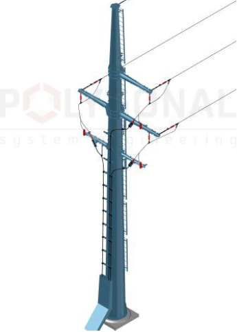
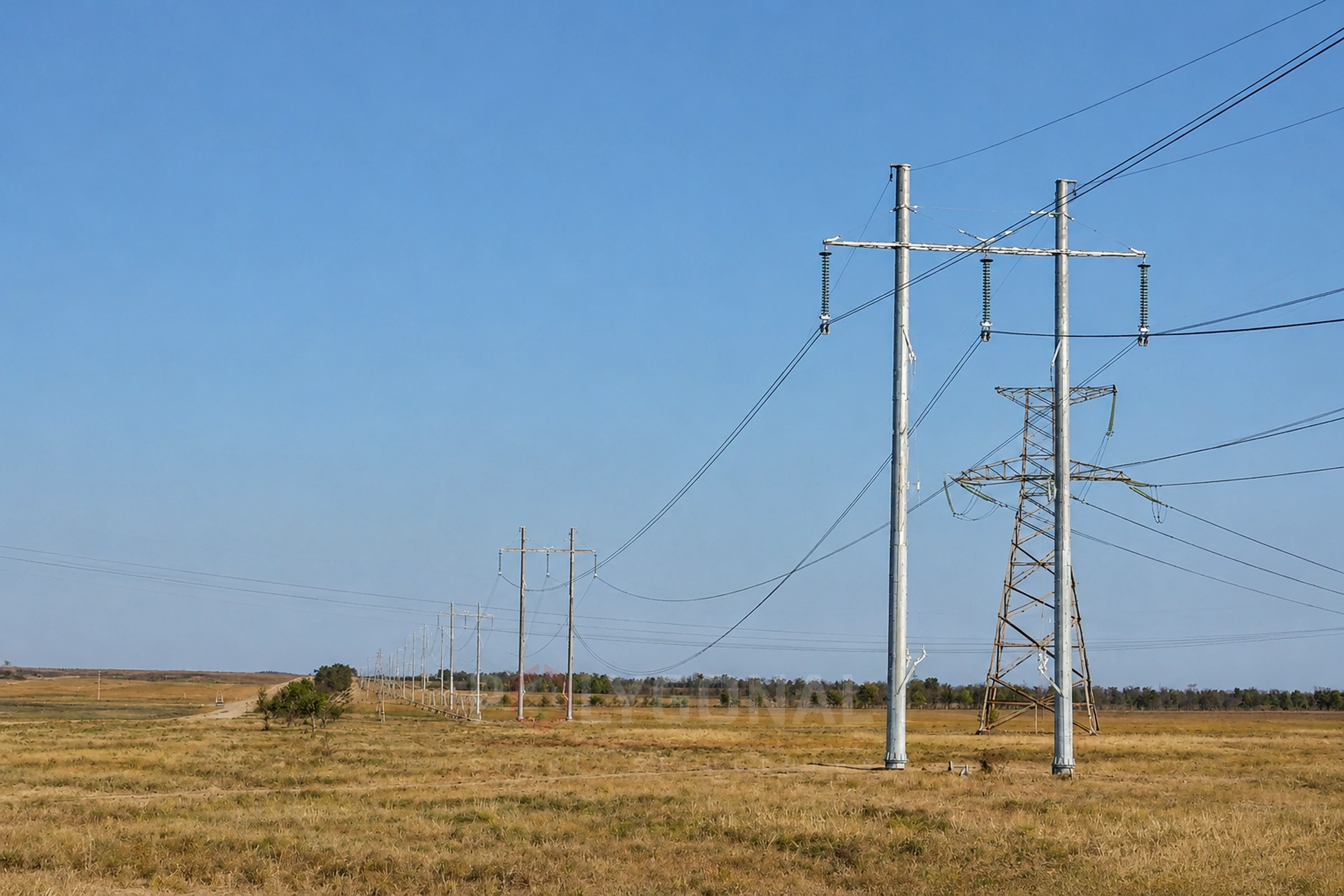
The PO-KV (cable-overhead transition support pole) is the pole on which a 35–110 kV overhead line passes into a cable. It is used on new lines and in reconstruction, to take a line out of an industrially developed area or to cross roads, railways and other engineering structures. It is most useful where development is dense, land allocation is limited and an open transition station cannot be built.
POLYGONAL engineers have developed a range of unified single- and double-circuit transition poles for 35–110 kV overhead lines. The standard solutions allow for the PUE requirements on the design of overhead and cable lines, and for a specific site those requirements are checked against the current edition of PUE. An order for PO-KV equipment is placed on the basis of a questionnaire. The typical design solution for the 35 kV PO-KV (TP-PO-KV-35-1F.19.01, 2019) is in the For Designers section: Cable-to-overhead transition structure 35 kV.
Conditions of use: ice regions 1–6, wind pressure regions 1–5, wind-during-icing regions 1–6; design outdoor air temperature from +40 °C to −40 °C; seismicity up to 6; moderate and intense conductor galloping; atmospheric pollution degree I–IV.
Structural solutions
The PO-KV is a steel multi-sided pole with a single shaft. Conductors are arranged in the traditional way, as on the standard unified steel lattice poles. In section the shaft is a regular sixteen-sided polygon, built from several sections. Without an earth wire the sections are joined by a slip (telescopic) joint; with one earth wire, the earth-wire peak (the top section) is joined through a flange. The sections carry attachment points for the crossarms of the conductors and of the cable terminations.
Shafts, crossarms and earth-wire peaks are made of S245 steel, category 4; flanges of S345, category 5 (DSTU 8539:2015); all other parts of S245, category 4. The structures are bolted with class 5.8 bolts and class 5 nuts, and the flanged joints with class 8.8 bolts and class 8 nuts. Spring washers keep the nuts from backing off; in flanged joints lock nuts are used.
The design calculations follow the Ukrainian PUE, DBN V.1.2-2:2006 and DBN V.2.6-198:2014; for a specific site the requirements are checked against the current edition of PUE. The PO-KV’s deformation in the horizontal and vertical planes meets the requirements for normal service. The pole is fixed to its foundation through a flange. The foundation itself is designed in the project for the specific site, depending on the geological data. All elements are hot-dip galvanised to DSTU EN ISO 1461:2024, with a coating 80–120 µm thick.
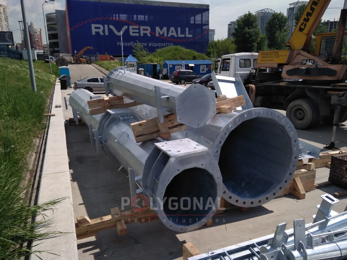
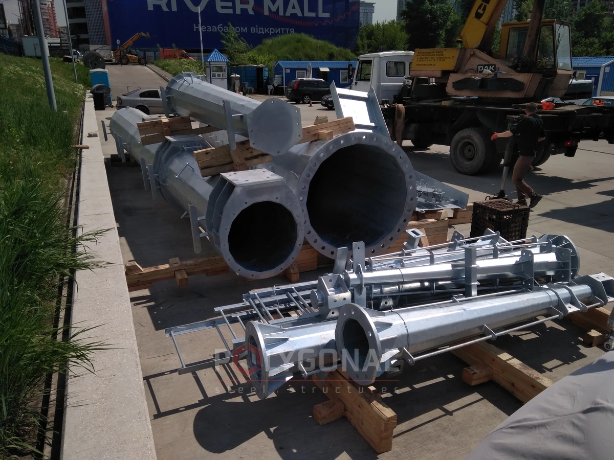
Delivery to site
A PO-KV transition point delivered to the site disassembled: the galvanised shaft sections and structural elements.

Electrical part
The design allows for the Ukrainian PUE requirements on protecting the overhead line from lightning overvoltage with earth wires. Phase conductors are attached at the ends of the crossarms and the earth wire to the body of the pole, using standard attachment points. A double-circuit strain suspension of the conductors can be fitted, and there are standard points for the earthing clamp that earths the earth wire. Strain insulator strings and line fittings are not in the PO-KV kit.
The bare overhead conductor is joined to the cable through cable terminations, and the design includes frames to hold them. The creepage length of the terminations’ external insulation is matched to the degree of atmospheric pollution at the site. The conductor connects to the termination through a factory-made specialised terminal clamp: crimped onto the conductor, bolted to the termination. Post-type non-linear surge arresters (SPD) mounted on the crossarm protect the terminations from impulse overvoltage; the arrester’s earthing conductor goes to the crossarm near the termination platform, with the insulation distances kept. Cable terminations and surge arresters are not in the kit.
Between the exit from the termination and the run underground, the cable is fixed on cable ladders made of profiles. The profiles have holes for factory-made cable clamps, and the unified fixing units let clamps for cables of different diameters be fitted without changing the design. The clamps are made of non-magnetic material that resists environmental, thermal and dynamic effects. The spacing of the fixing points and the cable’s bending radii must meet the cable manufacturer’s requirements. To protect the cable runs mechanically, a sheet-metal guard 3 m high from ground level is used. Cable clamps are not in the kit.
The cable screens are connected to the earthing device through terminal boxes. If the screens are earthed directly on the PO-KV side, the box is a three-phase screen earthing box with a common bus. If the screens are isolated from earth, it is a three-phase box with surge arresters, and the screen of each phase goes to the earth bus through an arrester. Each screen enters the box through a PPS connecting wire with polyethylene insulation and the same cross-section as the screen. The wire is brought in from below, so that moisture stays out. The metal body of the box is earthed with a separate conductor connected to the earthing device of the PO-KV. The box is fixed on the body of the pole and is not included in the kit.
Compatibility, service life and operation
Electrical equipment on the PO-KV can come from different manufacturers, as long as the types are chosen correctly: then it is compatible, convenient to operate and reliable in service. To make that possible, the design has unified attachment points: conductors of different cross-sections connect to the termination through one unified terminal clamp, terminations attach to their platforms, and there are cable fixings for cables of different diameters. A wide range of equipment therefore fits without changes to the pole. The sections of the multi-sided shaft match the dimensions of railway gondola cars and flat wagons, semi-trailers and trailers, so the pole can be shipped by different kinds of transport.
The design service life of the pole is 50 years, provided it is well made from the right steel grade, protected against corrosion, assembled accurately to the design instructions, and then operated and maintained as required.
Inspect the pole at the intervals the norms provide. Any area where the zinc coating is damaged should be found and restored by a method that gives reliable protection against the aggressive environment. In service, work at height calls for particular attention to safety. If the pole stands on uneven ground, prevent water in heavy rain from washing out the soil. Check the flow of the condensate drain from the pole base regularly, and clear tall vegetation within 1 m of the outline of the base.
Overhead-cable connection (PKZ) under the PUE
The Rules for the Arrangement of Electrical Installations (PUE), 2026 edition, call a link between an overhead line and a cable line, made on pole structures with cable terminations, an overhead-cable connection (PKZ). Built into above-ground switchgear, it is a transition point (PP; cl. 2.3.2). Where an overhead line goes into a 35–330 kV cable insert, a PKZ or PP must be made (cl. 2.3.68).
PKZ apparatus and cable terminations must sit on the pole so as not to hinder servicing the line’s insulating elements without de-energising (cl. 2.3.68). A cable insert must be protected against lightning overvoltage by surge arresters at both ends of the cable (cl. 2.5.122).
Every PKZ element that is to be earthed must be connected to the pole’s earth electrode; its resistance must meet Table 2.5.29, or cl. 1.7.98 where the PKZ has a disconnector (cl. 2.3.143). The point where the pole’s earthing conductor joins the earth electrode must be on the side of the structure opposite the cable entry, and the electrode’s branches must run at an angle of at least 90° from the cable direction (cl. 2.3.67). Screens of single-core cables must be earthed where they come onto the PKZ structures, so that the PKZ line part can be serviced without de-energising (cl. 2.3.124).
A separate, general requirement for cables near poles of lines above 1 kV: the horizontal clear distance from the outermost cable to the underground parts and earth electrodes of poles must be at least 7 m for poles protected by earth wires and 6 m for those without. If the cables lie in reinforced-concrete trays over the stretch of close approach (plus 5 m on each side), with no openings on the earth-electrode side, these distances may be reduced to 5 and 3 m respectively (cl. 2.3.67). Cables laid along PKZ structures must be shielded from ultraviolet radiation where their screen sheaths are not UV-resistant (cl. 2.3.19).
These are PUE requirements for a line design, not a product description; final values for a specific site come from the current PUE text.
Updated:
PO-KV transition pole: frequently asked questions
Where is the PO-KV pole used?
On 35–110 kV lines, at the point where an overhead line turns into a cable, both in new construction and in reconstruction. It is most useful in dense development, where an open transition point cannot be built.
How long does the pole last?
The design service life is 50 years, provided it is well made from the right steel grade, protected against corrosion, and operated and maintained as required.
What shape is the pole shaft?
16-sided: in section it is a regular hexadecagon. The sections are joined by a slip joint; in the version with an earth wire, the top section (the earth-wire peak) is joined through a flange.
What has to be ordered separately with the PO-KV?
Strain insulator strings, line fittings, cable terminations, surge arresters, cable clamps and earthing boxes. They are selected and ordered separately for the specific project.
Questionnaire: technical assignment form
Fill in the form and email it to us: we will prepare the KM-stage design documentation from it and calculate the price. The PDF is handy to print; the DOCX can be filled in on a computer.
Technical assignment form: overhead line pole
A questionnaire for preparing KM-stage design documentation for a steel polygonal overhead line pole: operating conditions, conductors, earth wires, insulator strings, clearances.
Related products: Overhead power line masts · Hot-dip galvanising
More on this topic: Typical Lattice Power Line Poles: Classification and Checks · Typical Lattice Transmission Poles 35–750 kV · Steel Multi-sided Poles for 6–10 kV Lines · Power Line Pole Types by Purpose: Suspension, Tension, Angle, Terminal · Power Line Protection Zone: Widths by Voltage Class · Distance Between Power Line Poles: What Determines the Span Length
Get a quote for your requirements
Send us your requirements — we will calculate the price and lead time.