
Cable-to-overhead transition structure 35 kV
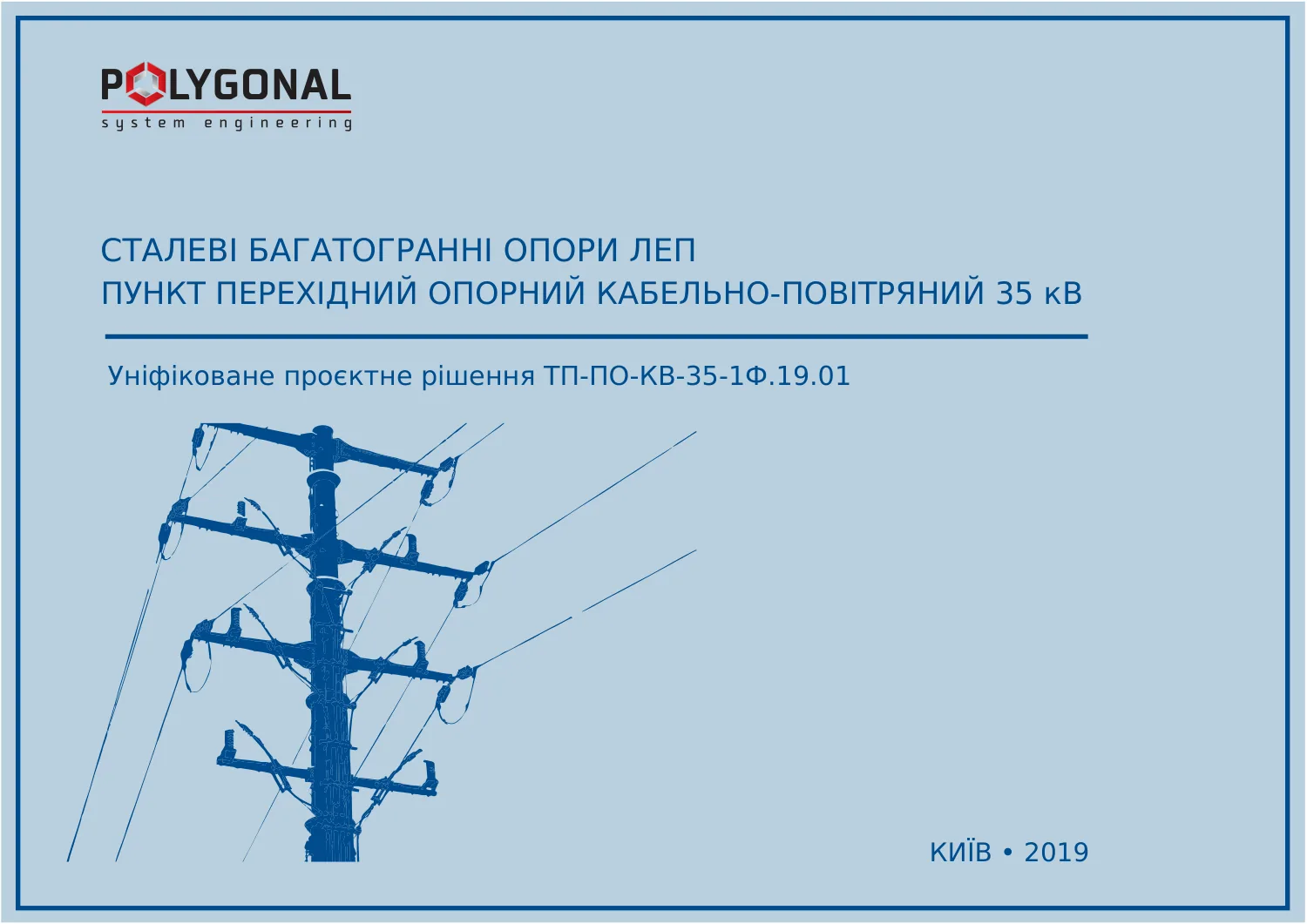
Unified design solution TP-PO-KV-35-1F.19.01 (2019): steel multi-sided power line poles. 12 pages. Document in Ukrainian.
Click the right or left half of the page to turn it; use the ← → keys, or swipe on a phone.
What’s in the catalogue
The «TP-PO-KV-35-1F.19.01» catalogue is a unified design solution for a 35 kV overhead-to-cable line transition structure, POLYGONAL, 2019.
Inside: general data and contents (p. 1), general notes — scope of application, design, electrical part, installation, operation (p. 2-5), installation schemes for both modifications and their cross-sections (p. 6-9), an order questionnaire (p. 10).
Key parameters
| Modification | Height, m | Sections | Wire crossarms | Cable sleeves | Ground wire |
|---|---|---|---|---|---|
| PO-KV-35-1F | 18.762 | 2 | at 15.5 and 18.5 m | 2 sleeves at 12.5 m | — |
| PO-KV-35-1F-T | 23.5 | 3 | at 15.5 and 18.5 m | 2 sleeves at 12.5 m | 1, at 23.5 m |
Post cross-section is a regular hexadecagon (16 sides). Sections are joined by a telescopic joint (the ground-wire post section — by a flange). From the TP-PO-KV-35-1F.19.01 catalogue.
Who it’s for
The transition structure is used to route a 35 kV overhead line out of an industrial site’s footprint, and to build crossings over roads, railways and other engineering structures — especially where dense development and a limited land plot rule out an open transition yard.
The pole is designed to carry ACSR wires AC 70/11, AC 95/16, AC 120/19, AC 150/24 and, in the -T modification, a TK-9.1 ground wire.
How to order
Manufactured to TU U 25.1-39573934-002:2018. Post cross-section is a regular hexadecagon, with a wire arrangement similar to the typical lattice pole U35-1+5. Fixed to the foundation through a flange. Hot-dip galvanising to DSTU EN ISO 1461:2024, coating thickness 80–120 microns. Design service life is 50 years.
Not included: cable end sleeves and surge arresters, cable clamps, shield-grounding terminal boxes, insulator strings and line fittings — these are selected separately for the specific equipment. To order, state the modification (with or without ground wire) and the input data in the questionnaire (p. 10 of the catalogue).
Worked example: reading the catalogue and choosing a modification
A sample task: a single-circuit 35 kV overhead line transitions to cable, and a ground wire is needed above the phase wires.
- Modification. With a ground wire: PO-KV-35-1F-T (p. 7); without one: PO-KV-35-1F (p. 6). The number of ground wires is stated in the questionnaire.
- Heights. The levels are the same in both modifications and are measured from the base of the post: cable terminations at 12.5 m, wire crossarms at 15.5 and 18.5 m, so the steps are 15.5 − 12.5 = 3.0 m and 18.5 − 15.5 = 3.0 m. In the -T version the ground wire is attached to the post at 23.5 m (also the overall post height in this version), so the ground-wire post rises 23.5 − 18.5 = 5.0 m above the top crossarm.
- Parts (pp. 6–9). Crossarms 3 + 2 = 5: three for the wires (two of 2800 mm and one of 3500 mm) and two for the cable terminations, 2500 mm each; two pole sections (plus the ground-wire post in -T); 11 cable ladders, and the access ladder and protective casing, one each.
Conditions of use and materials
| Parameter | Limits in the catalogue |
|---|---|
| Ice region | 1–6 |
| Wind pressure region | 1–5 |
| Wind pressure region during icing | 1–6 |
| Design outdoor air temperature | from −40 to +40 °C |
| Seismicity | up to 6 points on the MSK-64 scale |
| Wire galloping | moderate and intense |
| Atmospheric pollution degree | I–IV |
P. 2, clauses 2.1–2.5 (the MSK-64 scale is from item 10 of the questionnaire, p. 10); the regions are determined under the Ukrainian PUE:2026. Steel: posts, crossarms and ground-wire posts S245, flanges S345; bolts of flanged joints are class 8.8, all others 5.8.
What to prepare before ordering
The questionnaire (p. 10) has 40 items: 2 general (date, customer), 18 climatic (items 3–20), 13 on the overhead line (items 21–33), 6 on the cable line (items 34–39) and item 40, “Additional”. All fields are mandatory; where data is missing, a dash is entered.
Worth reading next:
Questions about the 35 kV cable-to-overhead transition structure
How do the PO-KV-35-1F and PO-KV-35-1F-T modifications differ?
By the ground-wire post and ground wire: PO-KV-35-1F-T is 4.7 m taller (23.5 m vs 18.762 m) and has 3 sections instead of 2 — the top ground-wire post section is joined by a flange.
Are cable sleeves and surge arresters included?
No, the pole has the standard mounting nodes (frames for sleeves, clamps for surge arresters), while the sleeves, arresters, cable clamps and shield-grounding terminal boxes are selected separately for the specific electrical equipment — the design is compatible with equipment from different manufacturers.
In what order is the pole installed?
The catalogue (p. 4) gives this sequence: the foundation; assembling the post with its crossarms and cable ladders on the ground; lifting it with a crane and bolting it to the foundation; then the cable terminations, cable, casing, end boxes, wires and surge arresters. The work must be done by a specialised organisation, and the customer exercises technical supervision.
What safety solutions are built into the design?
A fixed ladder with safety handrails for safe access to the pole (p. 3, clause 6.3), and a closed end box to which the cable screen leads are connected with insulated wire to rule out electric shock on touching the wire when voltage is present on the cable screen (clause 6.5).
Get a quote for your requirements
Send us your requirements — we will calculate the price and lead time.