
Home / Products / Overhead power line masts / Design of Power Line Poles and Foundations
Overhead power line masts
Design of Power Line Poles and Foundations
What data is needed to design steel power line poles, how multi-sided poles are built, and the principles for choosing and designing their foundations.
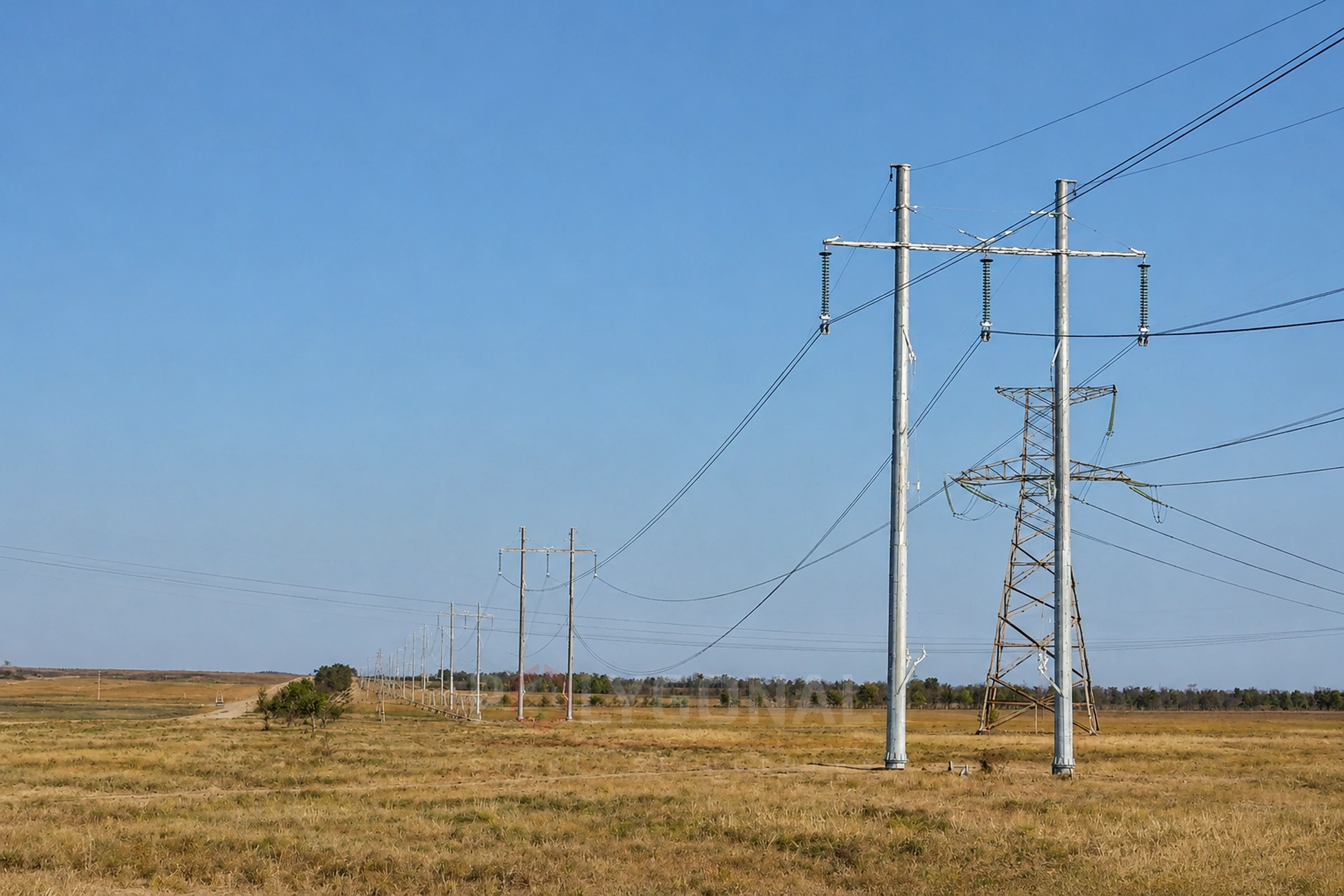
Contents
Input data for design
Standard unified poles often cannot cover everything a particular line demands. When the line or its route calls for it, the pole design is modified or a new one is developed. An individual design can take everything into account, from the structure itself to the possible method of erection.
Poles and their foundations are designed from the following data:
- results of the geotechnical surveys;
- seismicity of the construction area;
- purpose, structural and process features of the poles and foundations, and their operating conditions;
- loads acting on the multi-sided poles and foundations;
- existing buildings, and the effect new construction has on them;
- environmental requirements;
- size of the land plots available for the line structures;
- a technical and economic comparison of the possible design options, from which the best-value one is chosen.
Structural features of multi-sided power line poles
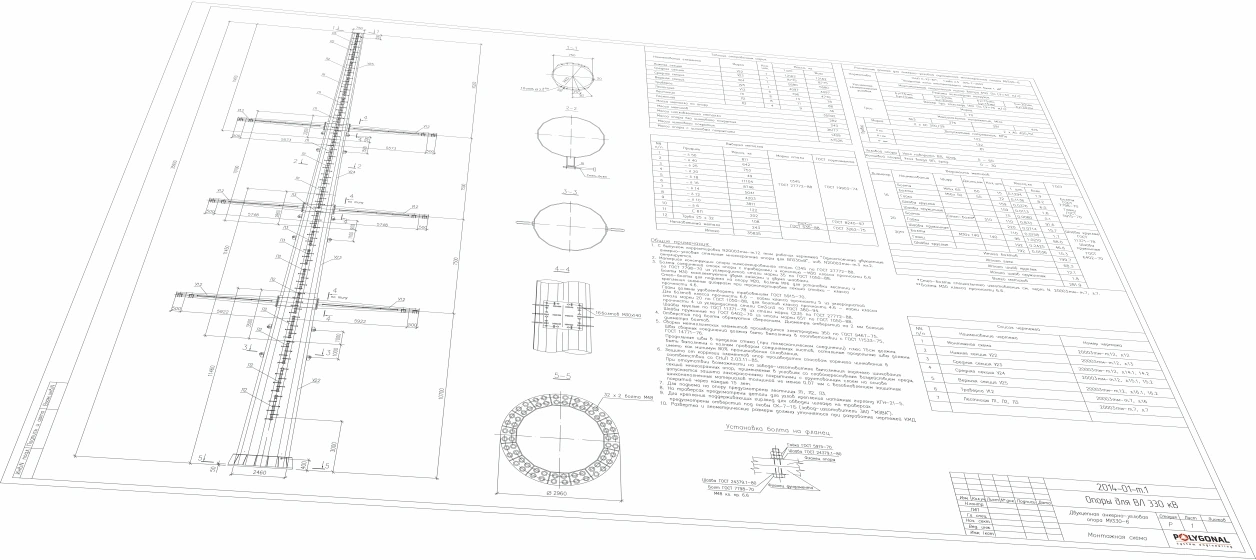
For steel multi-sided poles on 110–500 kV overhead lines, the wall must be at least 5 mm thick. The bottom diameter of the shaft, which is also the flange diameter, depends on the type and dimensions of the foundation. Depending on height, a shaft is made of one, two or several sections. Each section (a shipping element) is usually no longer than 12 m, because longer ones are awkward to transport.
Sections are joined in one of two ways: with flanges or with a slip (telescopic) joint. In a slip joint the joint length is taken as roughly one and a half to two diameters of the sections being joined (about 1.8 of the average diameter). The joint length has a tolerance at erection, so the finished shaft length can deviate, and the design allows for this: the permitted deviation is 10–12% of the joint length. Galvanised poles with a slip joint come with parts for pulling the sections together to a tight fit. The recommended procedure is to pull them together under a gradually increasing load, in steps that depend on the section diameter, until the sections stop moving relative to each other.
In flanged joints the bolts are arranged either on a circle (where shaft sections meet each other and the foundation) or around a rectangle (where multi-sided crossarms join the shaft). With flanged section joints, the erected shaft comes out at exactly the design height.
Multi-sided overhead line poles are classified the same way as standard steel power line poles under the PUE. Structurally they are either guyed or free-standing. Free-standing poles may have a single shaft or several (two or three); a two-shaft pole can be a portal pole with flexible or rigid internal bracing. By the joint between sections, poles are slip-joint or flanged. Crossarms on galvanised poles can be multi-sided, lattice or insulating.
A multi-sided crossarm is joined to the shaft by a flange. It can be set perpendicular or sloping up or down, and can be straight or curved. Lattice crossarms are bolted, both to the shaft and element to element. Insulating crossarms, which insulate the conductors and fix them to the pole, are attached to the shaft by specially developed units built on welded and bolted joints.
Phase conductors are fixed to the crossarms either through insulators or directly to insulating crossarms. With insulators, the string can be vertical, V-shaped or Λ-shaped. V-shaped strings are placed across the line axis in the space between phases; Λ-shaped ones go along the line axis.
Overhead power line masts
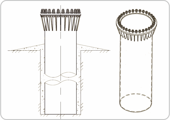
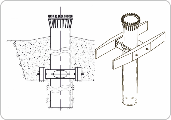
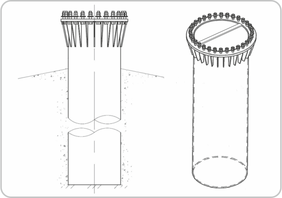
Designing power line pole foundations
A power line pole foundation is chosen individually: the solution depends on the soil conditions and on the load from the particular pole. The most common options are:
- single steel pile shells;
- single bored piles;
- screw piles with a steel grillage;
- steel pile shells with a steel grillage;
- screw, driven or bored piles, or steel pile shells, under a cast-in-place reinforced concrete grillage;
- cast-in-place foundations.
The piles come in several variants: a pile shell; a pile shell reinforced with two crossbars; a vibro-driven pile shell; a bored pile; a multi-pile foundation of bored piles; screw piles with a cast-in-place or steel grillage.
The number of piles and their size are set to make maximum use of the strength of the pile material and of the properties of the foundation soils at the design load allowed on a pile. Pile length depends on the soil conditions, the level of the bottom of the grillage and the equipment available. Foundations of single bored piles or steel pile shells 0.7 to 2.5 m in diameter can be embedded as deep as 15–20 m, depending on loads and soils, though the best depth is 4–6 m. In foundations with a grillage, large-diameter piles (at least 500 mm) are recommended in groups of two, three, four, six or more; small-diameter piles (under 500 mm) and screw piles in groups of two, four, eight, twelve or more. Recommended pile length in piled foundations is up to 12 m.
Designing foundations for multi-sided poles
The design and size of the fixing of a multi-sided pole depend on the magnitude and direction of the loads on the foundation (erection loads included) and on the construction technology. Single-shaft multi-sided poles concentrate force on the ring base of the shaft, so the main design load on the foundation is the bending moment at ground level. To carry large bending moments, the recommended options are piled foundations of single large-diameter piles (pile shells or bored piles) or multi-pile foundations with the piles spaced as far apart as possible. The distance between pile axes must be at least three pile diameters, or, for screw piles, at least three blade diameters.
Large-diameter bored piles are mostly designed as single piles. Steel pile shells are designed, depending on loads, either as single piles or as pile clusters (two, three, four, six or more piles), and screw piles as pile clusters. When more load capacity is needed from steel pile shells or large-diameter bored piles, the recommended way to get it is to increase the embedment depth, not the diameter. In sands, and in hard, semi-hard and stiff-plastic clay soils, fixing without crossbars is recommended. Steel pile shells are then driven with minimum disturbance of the soil structure: either without removing soil or with a borehole of the same diameter as the pile shell.
Where a foundation has crossbars, they are set perpendicular to the resultant of the loads on the pole. With equal tension of conductors and earth wires in adjacent spans, the direction of the resultant coincides with the bisector of the angle adjacent to the line angle.
The grillage is either cast-in-place reinforced concrete or steel, depending on how the pole is fixed. A reinforced concrete grillage stiffens the foundation and lowers the pressure on the soil under large bending moments; a steel one is used with steel pile shells and screw piles. A grillage can sit below ground level, which improves appearance and environmental friendliness (greenery is planted on the surface) and reduces the land taken, but the buried elements then need extra waterproofing and corrosion protection.
On frost-heaving soils, provision is made to prevent or reduce the effect of frost heave forces. Where the soil includes organo-mineral and organic layers, the lower ends of the piles are sunk deeper than those layers, and the calculation follows the scheme of a high pile grillage, disregarding the load capacity of the layers.
Updated:
Reviewed by: V.V. Padalka, Chief Project Engineer
Designing power line poles and foundations: frequently asked questions
How thick must the wall of a multi-sided pole be on a 110–500 kV line?
At least 5 mm. The bottom diameter of the shaft (the flange diameter) depends on the type and dimensions of the foundation.
How long can a pole section be?
Usually no more than 12 m, because longer sections are awkward to transport. Sections are joined with flanges or with a slip (telescopic) joint.
How deep do bored piles go?
As deep as 15–20 m, depending on loads and soils, though the best depth is 4–6 m. Such piles are 0.7 to 2.5 m in diameter.
How close together can piles be placed in a multi-pile foundation?
Pile axes must be at least three pile diameters apart (for screw piles, at least three blade diameters).
Questionnaire: technical assignment form
Fill in the form and email it to us: we will prepare the KM-stage design documentation from it and calculate the price. The PDF is handy to print; the DOCX can be filled in on a computer.
Technical assignment form: overhead line pole
A questionnaire for preparing KM-stage design documentation for a steel polygonal overhead line pole: operating conditions, conductors, earth wires, insulator strings, clearances.
Related products: Overhead power line masts · Steel structure design (structural and detail drawings)
More on this topic: Typical Lattice Power Line Poles: Classification and Checks · Typical Lattice Transmission Poles 35–750 kV · Steel Multi-sided Poles for 6–10 kV Lines · Power Line Pole Types by Purpose: Suspension, Tension, Angle, Terminal · Power Line Protection Zone: Widths by Voltage Class · Distance Between Power Line Poles: What Determines the Span Length
Get a quote for your requirements
Send us your requirements — we will calculate the price and lead time.