
Home / Products / Overhead power line masts / Distance Between Power Line Poles: What Determines the Span Length
Overhead power line masts
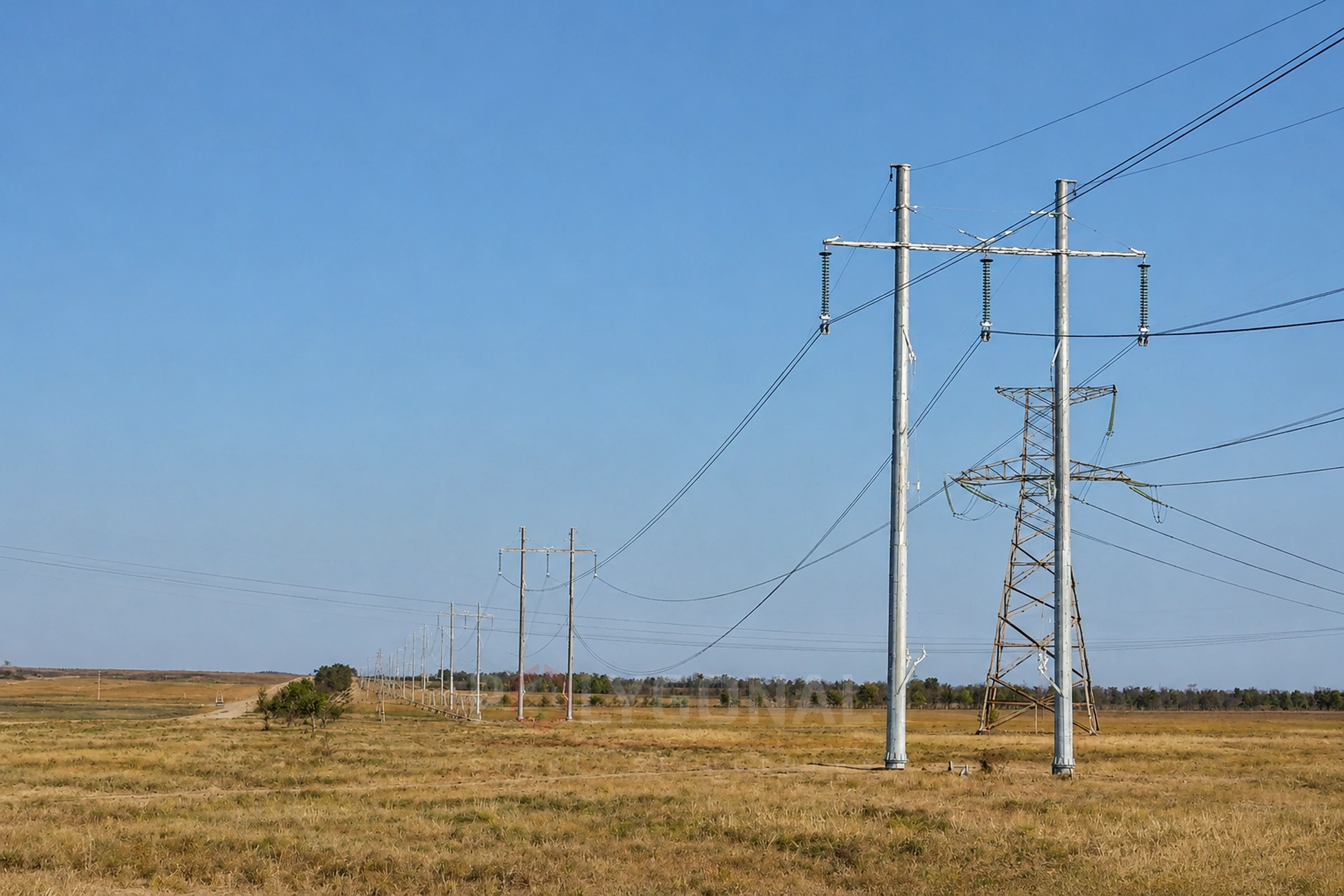
Distance Between Power Line Poles: What Determines the Span Length
People often search for a ready-made table of distances between power line poles by voltage class. We explain honestly: no such fixed table exists in PUE (2026 edition) — the span length is the result of a calculation for a specific line. PUE sets upper limits for the distance between tension poles; more on that below.
Contents
- Why there is no fixed span table
- Length of a tension section: what the PUE limits
- What determines the span length in practice
- Distance between conductors in a span: the PUE formula
- Voltage class and the minimum conductor height above ground
- Types of span: clearance, weight, wind
- How span length affects the pole
- What data we need to select poles for your project
Why there is no fixed span table
The Rules for the Arrangement of Electrical Installations (PUE) in the 2026 edition (the part on overhead power lines above 1 kV) do not set the span length as a fixed number by voltage class. Instead, PUE sets a calculation method: conductor sag, wind and ice loads, reliability factors depending on pole height, terrain type and the design recurrence period of climatic effects. The 2017 edition of PUE (order of 21.07.2017 No. 476) has been replaced by the 2026 edition (PUE:2026). The values given here were checked against its text, and the final values for a specific line are taken by the designer from the current text.
This means that even for the same voltage, the span can differ significantly depending on the conductor grade and cross-section, the wind region, the pole type and the route’s terrain.
Length of a tension section: what the PUE limits
PUE gives no fixed span length, but it does limit the length of a tension section, that is, the distance between tension poles (cl. 2.5.135). Where the tension poles go is decided by the conditions of building and operating the line and by the working conditions of the pole structure itself. The upper limits depend on voltage, on how the conductors are fixed and on the terrain:
| Line | Maximum distance between tension poles |
|---|---|
| New lines of 35 kV and above with suspension-type fixing of the conductors | 10 km |
| The same lines in hard-to-reach terrain or in especially difficult natural conditions | 5 km |
| Lines of 35 kV and below with conductors on pin insulators, ice regions 1–3 | 1.5 km |
| Lines of 35 kV and below with conductors on pin insulators, ice regions 4 and above | 1 km |
| Lines of 20 kV and below with suspension insulators | 3 km |
Values from PUE (2026 edition), cl. 2.5.135. These are upper limits for a design, not typical distances. In mountainous or heavily broken terrain in ice regions 3 and above, tension poles are recommended at passes and at other points that rise sharply above the surrounding ground.
What determines the span length in practice
- conductor grade and cross-section — determine the allowable sag and mechanical strength;
- the route’s wind and ice region — the harsher the climatic loads, the more conservative the span margin;
- pole type — suspension, tension or angle poles carry loads differently (see the article Power Line Pole Types by Purpose);
- vertical clearance requirements — the height of conductors above the ground and distances to buildings and crossings with other objects (see the article Power Line Protection Zone);
- the route’s terrain and obstacles: rivers, roads, other lines.
Distance between conductors in a span: the PUE formula
Span length enters the PUE rules through the sag: the longer the span, the larger the sag, and with it the distance between conductors that their operation in the span requires (insulation distances and lightning-protection conditions are checked separately, cl. 2.5.96). For lines with supporting insulator strings (other than lines with covered conductors) and a horizontal arrangement of conductors, the minimum distance between conductors in the span is calculated by these formulas (cl. 2.5.97):
- up to 330 kV: d = 1.0 + U/110 + 0.6·√f;
- 500 and 750 kV: d = 1.0 + U/150 + 0.6·√f + 2r.
Here d is the horizontal distance between undeflected conductors, m; U is the line voltage, kV; f is the greatest sag of the conductor at the highest temperature or under ice without wind, taken for the clearance span, m; r is the radius of the conductor bundle in the phase, m.
The distances are taken for the sag of the clearance span (defined below, in the section on span types). If some individual spans that result from pole placement (no more than 10 % of all spans) are longer than the clearance span by no more than 25 %, the distance found for the clearance span need not be increased. With a greater excess the distances are checked separately by the formulas (cl. 2.5.96).
A conditional example (the sags are chosen arbitrarily). A 110 kV line with a sag f = 6 m: d = 1.0 + 110/110 + 0.6·√6 = 1.0 + 1.0 + 1.47 ≈ 3.47 m. A 35 kV line with a sag f = 4 m: d = 1.0 + 35/110 + 0.6·√4 = 1.0 + 0.32 + 1.2 ≈ 2.52 m.
On the same lines, with a mixed or vertical arrangement of conductors, the rules differ (cl. 2.5.98). On intermediate poles with sags up to 16 m the distance is taken from Table 2.5.22 (moderate galloping of conductors) or Table 2.5.23 (intense galloping); in ice regions 3–6 a check by formula (2.5.24) is added to Table 2.5.22, and the greater of the two values is used. On intermediate poles with sags over 16 m the distance is calculated by formula (2.5.24). On tension poles of 35–750 kV it is calculated by formulas (2.5.22) and (2.5.23), and the minimum horizontal offset of conductors in adjacent tiers should, as a rule, be no less than the values in Table 2.5.24.
Voltage class and the minimum conductor height above ground
Voltage class does not set the span length by itself, but it affects it through clearance: as the voltage rises, the minimum height of the conductor above the ground at the lowest point of the span, as a rule, increases (from 7 to 15.5 m in the table below). This is a clearance, not a ready-made span length: the longer the span, the greater the sag and the higher the conductor has to be hung. Pole heights are covered in Transmission Pole Height by Voltage Class; distances to buildings and the width of the protection zone are in Power Line Protection Zone.
For populated areas, the minimum vertical distance between a conductor and the ground surface for normal operation of the line, measured when the conductor sags the most, is set by PUE (2026 edition), Table 2.5.33. Values by voltage class:
| Line voltage class | Minimum conductor height above the ground in populated areas, m |
|---|---|
| up to 35 kV | 7 |
| 110 kV | 7 |
| 150 kV | 7.5 |
| 220 kV | 8 |
| 330 kV | 11 |
| 500 kV | 15.5 |
Values from PUE (2026 edition). For unpopulated and hard-to-reach terrain, PUE allows smaller values (Table 2.5.30), so these figures do not apply to the whole route. There is no 750 kV row: 750 kV lines may not be routed through populated areas (cl. 2.5.169).
What else PUE requires in populated areas
PUE (2026 edition), cl. 2.5.169, requires lines of 35–500 kV, as a rule, to be routed outside the residential parts of settlements. Where a line passes over streets and access roads, a conductor whose aluminium part has a cross-section smaller than 185 mm² is also checked for the case of a conductor breaking in the adjacent span: at the mean annual temperature, without allowing for current heating of the conductor, the distance to the ground must then be at least 5.5 m (for lines up to 220 kV; cl. 2.5.172, Table 2.5.33). For lines in a specially designated city corridor, and for conductors of 185 mm² and more, this check is not required.
Types of span: clearance, weight, wind
Calculations use several distinct span concepts, and they should not be confused:
- clearance span — a span whose length is set by the required clearance of the conductor above the ground, assuming the poles stand on level ground;
- weight span — a notional length used to work out the vertical load on a pole from the weight of the conductor and ice (on level ground, half the sum of the two adjacent span lengths; with height differences between poles it is set by the positions of the lowest points of the conductor’s sag in the adjacent spans);
- wind span — a notional length for the pole’s horizontal wind-load calculation (usually half the sum of the adjacent span lengths, so on sloping ground or with height differences it can differ from the weight span).
A pole is designed for these calculated values, not simply for the visible distance to the next pole.
How span length affects the pole
For the same horizontal tension and the same load per metre of conductor, the sag grows roughly in proportion to the square of the span: a span twice as long gives about four times the sag. So long spans need higher suspension points, and as the wind and weight spans grow, so do the loads on the pole and foundation (for loads on overhead lines in general, see Loads on Overhead Lines and Transmission Poles).
A shorter span relieves each pole but adds to their number, so the span is chosen together with the pole type. Pole types are compared in Power Line Poles: Multi-sided, Lattice or Reinforced Concrete.
What data we need to select poles for your project
The span length is set by the line design. From the customer’s input data — voltage class, conductor grade and cross-section, number of circuits, wind and ice region, route type — we design the poles: we prepare KM/KMD drawings and carry out verification calculations. Send us this data or fill in the technical specification form and we will select the pole design for your project.
Updated:
Reviewed by: V.V. Padalka, Chief Project Engineer
Distance between power line poles: frequently asked questions
Does PUE have a table of distances between poles by voltage class?
No. In the 2026 edition, PUE sets a method for calculating the span (sag, loads, reliability factors), not fixed metres by voltage. The span is calculated separately for each line. PUE gives upper limits in kilometres not for the span but for the distance between tension poles (cl. 2.5.135).
Why do different sources give different distances for the same voltage?
Because such sources give indicative values for particular conditions — typical pole series or individual projects; they are not a code requirement. The actual span depends on the conductor grade, wind region, pole type and terrain, so the figures differ even at the same voltage.
What do I need to send to select poles for my project?
The voltage class, conductor grade and cross-section, number of circuits, the construction site’s wind and ice region, and the route type. If you do not know something, fill in the technical specification form and leave the fields you do not know blank — we will clarify.
What is the minimum distance between a power line conductor and the ground in a populated area?
Under normal operation of the line this distance depends on the voltage class. Under PUE (2026 edition), Table 2.5.33: 7 m for lines up to and including 110 kV, 7.5 m for 150 kV, 8 m for 220 kV, 11 m for 330 kV, 15.5 m for 500 kV.
Related products: Overhead power line masts
More on this topic: Typical Lattice Power Line Poles: Classification and Checks · Typical Lattice Transmission Poles 35–750 kV · Steel Multi-sided Poles for 6–10 kV Lines · Power Line Pole Types by Purpose: Suspension, Tension, Angle, Terminal · Power Line Protection Zone: Widths by Voltage Class · Steel Multi-sided Poles for 35 kV Lines
Get a quote for your requirements
Send us your requirements — we will calculate the price and lead time.