
Home / Products / Overhead power line masts / Transmission Pole Height by Voltage Class 35–750 kV: Table
Overhead power line masts
Transmission Pole Height by Voltage Class 35–750 kV: Table
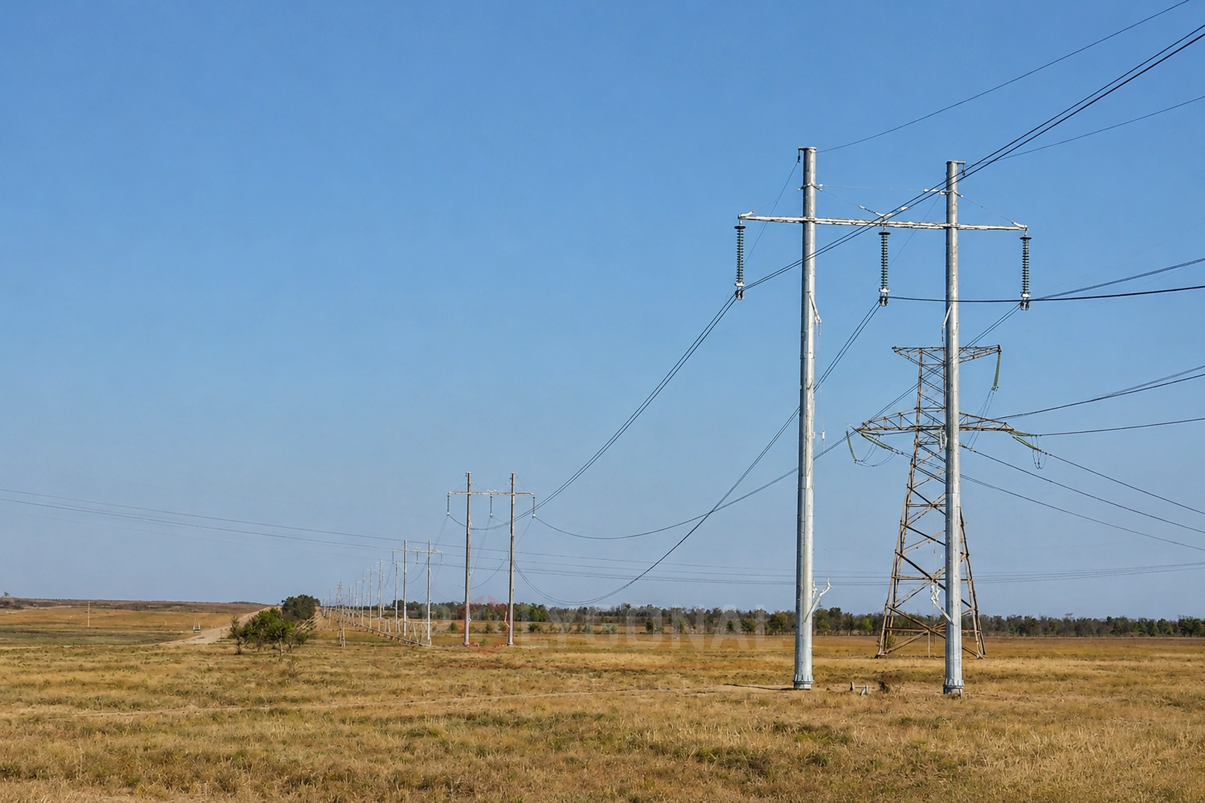
Voltage class fixes only part of a transmission pole’s height. The pole type (tension-angle, intermediate or crossing) and the specific designation matter too. Below are the height ranges from our line-up of typical lattice poles for 35–750 kV, first by voltage class and then by pole type.
Contents
- Height range by voltage class
- Height by pole type
- Why the same voltage class can span such a wide height range
- What about 0.4–10 kV lines
- Multi-sided poles as an alternative to lattice
- How pole height relates to span and foundation
- Example: choosing the height of a 110 kV intermediate pole
- Checklist and common mistakes
- Pole height and price
- Minimum conductor height above the ground under the PUE
- Pole mass by height and type
- How much mass each metre of height adds
Height range by voltage class
The table gives the height to the underside of the cross-arm, which is the dimension listed in the catalogue of typical poles. The full height of the structure, with the earth-wire peak and lightning protection, is noticeably greater. Take that figure from the typical design for the designation in question.
| Voltage class | Height to underside of cross-arm, m |
|---|---|
| 35 kV | 10.0–19.5 |
| 110 kV | 10.5–67.5 |
| 220 kV | 10.5–79.0 |
| 330 kV | 10.7–81.0 |
| 500 kV | 17.0–100.0 |
| 750 kV | 20.0–45.0 |
The range covers the designations in our catalogue of typical poles for each class: tension-angle (У), intermediate (П) and crossing (ПП), including added heights (“+5”, “+9” etc.); the designations use Cyrillic letters, as in the catalogue. For 500 kV, designations with two height values (“12 and 17” etc.) are not counted; they are listed in the catalogue. The full list of designations with the height and mass of each is in the article Typical Lattice Transmission Poles 35–750 kV.
Height by pole type
The same designations, grouped by pole type. In every class the lowest pole is a tension-angle one; in the 110–500 kV classes the tallest are crossing poles.
| Voltage class | Tension-angle (У), m | Intermediate (П), m | Crossing (ПП), m |
|---|---|---|---|
| 35 kV | 10.0–19.5 | 11.0–15.0 | — |
| 110 kV | 10.5–24.5 | 15.0–23.0 | 37.5–67.5 |
| 220 kV | 10.5–24.5 | 15.0–30.5 | 38.0–79.0 |
| 330 kV | 10.7–24.7 | 17.5–31.2 | 40.0–81.0 |
| 500 kV | 17.0–30.0 | 24.0–42.0 | 40.0–100.0 |
| 750 kV | 20.0–35.0 | 28.8–45.0 | — |
Height to the underside of the cross-arm, including added heights. A dash means our catalogue has no poles of that type for the class. For 500 kV, designations with two height values are not counted.
Why the same voltage class can span such a wide height range
In the 110–500 kV classes the tallest poles are crossing poles, used where a line crosses rivers, ravines or other lines. The 35 and 750 kV classes have no crossing poles in our range, so the tallest poles there are those with the largest added height for difficult terrain.
The lowest pole in every class is a tension-angle pole with no added height. The lowest intermediate pole of the same class stands higher than the lowest tension-angle one.
The upper end of the 750 kV range sits below that of 500 kV, and that is not an error: our 750 kV range has fewer pole types and no extra-tall crossing variants at all.
What about 0.4–10 kV lines
Distribution lines of 0.4–10 kV usually run on wooden or reinforced-concrete poles (SV-95, SV-105 and similar). That is a different type of structure, outside our lattice range, so we give no heights for it here.
The length of a reinforced-concrete pole is in its designation, as a number of decimetres: SV-95 is a 9.5 m pole, SV-105 is 10.5 m, SV-110 is 11 m.
For these lines we make steel cross-arms, caps and brackets, see Overhead Line Fittings 0.4–10 kV. For 6–10 kV we also make steel multi-sided poles: Steel Multi-sided Poles for 6–10 kV Overhead Lines.
Multi-sided poles as an alternative to lattice
The tables above cover our typical lattice poles. For 6–220 kV lines we also make multi-sided poles: one compact shaft with a closed profile and hot-dip galvanising. It is less prone to corrosion and vandalism, and it takes up less ground for the foundation than the wide base of a lattice pole. A fuller comparison of multi-sided, lattice and reinforced-concrete poles is in Power Line Poles: Multi-sided, Lattice or Reinforced Concrete.
Examples by voltage class: 35 kV lines, 110 kV lines, 220 kV lines.
How pole height relates to span and foundation
A taller pole generally allows a longer span to the next one for the same conductors and loads: a higher suspension point holds the required conductor-to-ground clearance over a greater distance. The trade-off is at the base. Wind puts a larger bending moment on a taller pole, so it needs a larger and deeper foundation. What sets the exact span length is covered in Distance Between Power Line Poles.
Example: choosing the height of a 110 kV intermediate pole
This is a simplified example with assumed data; the real values come from the line design. Take a populated area, level terrain, a maximum sag of the lowest conductor f = 6 m and an insulator string with fittings λ = 1.5 m. The minimum conductor height above the ground for 110 kV in a populated area is 7 m under the Rules for the Arrangement of Electrical Installations (PUE), 2026 edition, Table 2.5.33 (see also Distance Between Power Line Poles).
As an approximation, we take the height to the underside of the cross-arm from the catalogue of typical poles as the height where the lowest conductor’s insulator string is attached. The required height to the underside of the cross-arm is then 7 + 6 + 1.5 = 14.5 m. On a 15 m pole the lowest point of the conductor sits 15 − 1.5 − 6 = 7.5 m above the ground, a margin of only 0.5 m. The next height of 110 kV intermediate poles in the catalogue is 19 m (for example, П110-1): 19 − 1.5 − 6 = 11.5 m, a margin of 4.5 m.
This is a simplification: the catalogue height to the underside of the cross-arm is not the actual attachment height of the insulator string, so the design also accounts for where the cross-arms sit, the terrain under the conductor and a margin for inaccuracies.
Checklist and common mistakes
- clearance to the ground and to crossings under the current edition of PUE;
- sag, insulator string length, height differences along the route;
- added height and the foundation for a taller pole.
A typical mistake is to take the height to the underside of the cross-arm (as given in the catalogue) for the full height of the pole. Another is to read the ranges in the tables as a code requirement.
Pole height and price
Height drives the mass of the pole, the shaft diameter and the foundation, and through them the cost. Within one voltage class the price can differ several times over. Indicative prices by voltage class are on the Power line pole prices page.
Minimum conductor height above the ground under the PUE
Pole height is chosen to fit the clearance. Under the PUE (2026 edition), in normal operation and at the largest sag, the lowest conductor must not be closer to the ground than the table shows (minimum distance, m).
| Voltage class | Populated area | Non-populated area | Hard-to-reach terrain | Over a road carriageway |
|---|---|---|---|---|
| 35 kV | 7 | 6 | 5 | 7 |
| 110 kV | 7 | 6 | 5 | 7 |
| 150 kV | 7.5 | 6.5 | 5.5 | 7.5 |
| 220 kV | 8 | 7 | 6 | 8 |
| 330 kV | 11 | 7.5 | 6.5 | 8.5 |
| 500 kV | 15.5 | 8 | 7 | 9.5 |
| 750 kV | not allowed | 12 | 10 | 16 |
PUE (2026 edition): Table 2.5.33 and cl. 2.5.171 for populated areas; Table 2.5.30 and cl. 2.5.160 for non-populated and hard-to-reach terrain; Table 2.5.46 and cl. 2.5.216 for roads of all categories. A 750 kV line must not be routed through a populated area (cl. 2.5.169). The catalogue of typical poles has no 150 kV class; that row comes from the PUE alone. The designer takes the final values for a specific line from the current text of the PUE.
Pole mass by height and type
The table gives the lightest and the heaviest pole of each class and type in our catalogue of typical poles (mass without zinc, t), for the same designations as the height ranges above.
| Voltage class | Tension-angle (У), t | Intermediate (П), t | Crossing (ПП), t |
|---|---|---|---|
| 35 kV | 1.6–6.8 | 1.5–2.3 | — |
| 110 kV | 3.2–14.6 | 1.9–6.8 | 29.9–58.5 |
| 220 kV | 6.2–23.4 | 2.8–10.4 | 33.7–79.9 |
| 330 kV | 10.5–38.3 | 4.5–12.0 | 65.3–142.8 |
| 500 kV | 12.1–35.8 | 6.3–22.9 | 88.3–206.3 |
| 750 kV | 29.5–67.6 | 10.7–27.6 | — |
The zinc coating adds a little; the full data by designation is in Typical Lattice Transmission Poles 35–750 kV. A dash means our catalogue has no such poles for the class.
How much mass each metre of height adds
Take the 110 kV designations for which the catalogue lists several heights (as above, the height to the underside of the cross-arm) and divide the gain in mass by the gain in height.
| Designation | Height to underside of cross-arm, m | Mass without zinc, kg | Gain per 1 m, kg |
|---|---|---|---|
| У110-1 (tension-angle) | 10.5 → 24.5 | 5,040 → 11,299 | ≈ 447 |
| П110-1 (intermediate) | 19 → 23 | 1,895 → 2,469 | ≈ 144 |
| ПП110-1 (crossing) | 37.5 → 67.5 | 29,863 → 54,239 | ≈ 813 |
Example of the calculation for У110-1: (11,299 − 5,040) ÷ 14 ≈ 447. This is an average for the designation, not a norm: the catalogue gives a separate mass for each height. П110-1 has only two heights there, 19 and 23 m.
Updated:
Transmission pole height: frequently asked questions
How low can a 110 kV transmission pole be?
In our range, 10.5 m to the underside of the cross-arm. Those are the tension-angle poles У110-1 and У110-2 with no added height. Intermediate 110 kV poles start at 15.0 m and crossing poles at 37.5 m.
Why is the tallest 750 kV pole shorter than the tallest 500 kV one?
It comes down to what the catalogue contains: there are no crossing poles for 750 kV, while for 500 kV they reach 100 m. Compare poles of the same type and the 750 kV pole is taller than the 500 kV one: tension-angle 20.0–35.0 m against 17.0–30.0 m, intermediate 28.8–45.0 m against 24.0–42.0 m (see the table by pole type).
Where can I look up the height and mass of a pole by its designation?
In Typical Lattice Transmission Poles 35–750 kV. Every designation is listed there with its height to the underside of the cross-arm and its mass, both without and with the zinc coating.
Does the minimum conductor height above the ground stay the same along the whole route?
No, it depends on the terrain. Under the PUE (2026 edition), Tables 2.5.33 and 2.5.30, a 110 kV conductor must be at least 7 m above the ground in populated areas, 6 m in non-populated areas and 5 m in hard-to-reach terrain.
Can I take the tallest pole just in case?
Usually not. A taller pole is heavier and puts a larger wind-induced bending moment on its base, so it needs a larger foundation. The height is chosen by calculation against the required clearance.
How much does a 19 m 110 kV intermediate pole weigh?
In the catalogue, П110-1 with 19 m to the underside of the cross-arm weighs 1,895 kg without the zinc coating and 1,969 kg with it. Intermediate 110 kV poles there run from 1.9 to 6.8 t, depending on the designation.
How does pole mass depend on height?
It grows, but not equally for all types: in the catalogue each extra metre adds about 447 kg to У110-1, 144 kg to П110-1 and 813 kg to ПП110-1.
Related products: Overhead power line masts
More on this topic: Typical Lattice Power Line Poles: Classification and Checks · Typical Lattice Transmission Poles 35–750 kV · Steel Multi-sided Poles for 6–10 kV Lines · Power Line Pole Types by Purpose: Suspension, Tension, Angle, Terminal · Power Line Protection Zone: Widths by Voltage Class · Distance Between Power Line Poles: What Determines the Span Length
Get a quote for your requirements
Send us your requirements — we will calculate the price and lead time.