
Home / Products / Overhead power line masts / Steel Multi-sided Poles for 220 kV Lines
Overhead power line masts
Steel Multi-sided Poles for 220 kV Lines
Why multi-sided poles are used on 220 kV lines in urban and restricted conditions, which types are made and how they are calculated.
Contents
Use of multi-sided poles on 220 kV lines
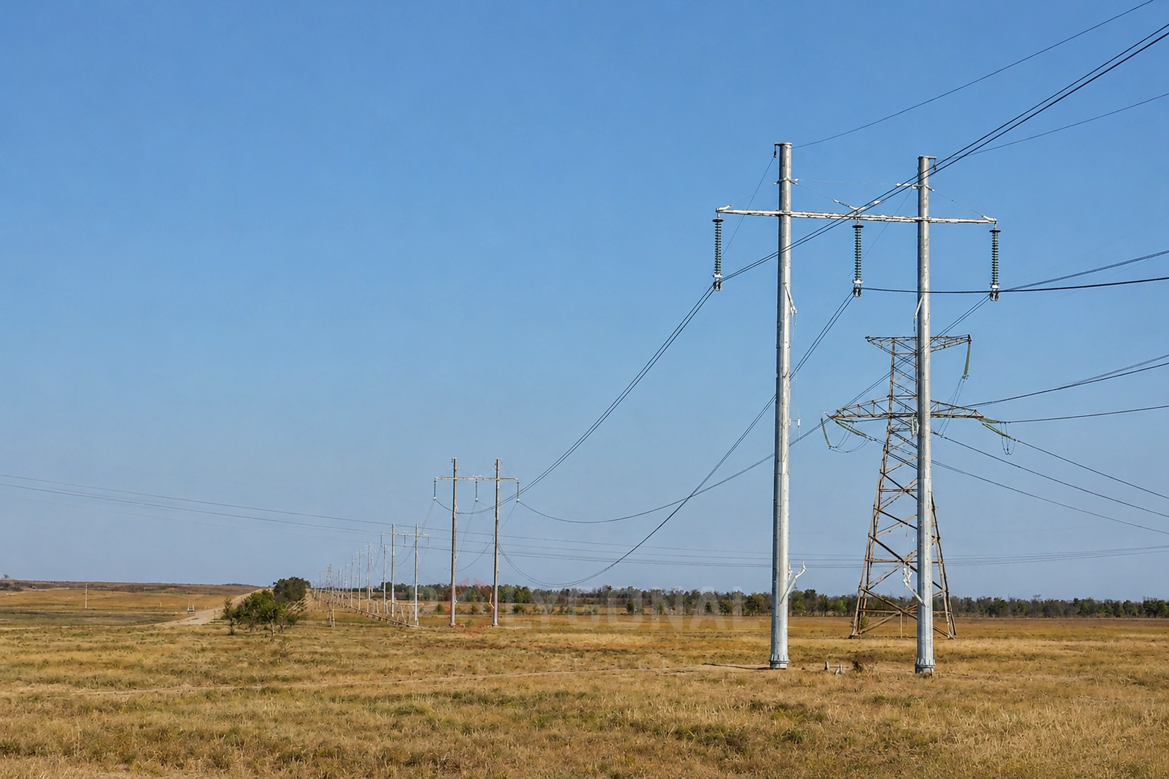
POLYGONAL designs and manufactures steel multi-sided poles for 220 kV overhead power lines. Using only the standard steel lattice poles on 220 kV lines makes them hard to install in a number of cases, especially in urban and restricted conditions. In such conditions it is more appropriate to use new-generation angle-anchor poles based on steel multi-sided shafts.
Multi-sided steel poles are lighter than steel lattice poles, can be made in compact sections of a given length, are not prone to breakage or damage in transport and reduce the amount of transport and handling work. They can be used in wind and ice regions I–IV, in unpopulated and populated areas, and in mildly and moderately aggressive environments.
Overhead power line masts
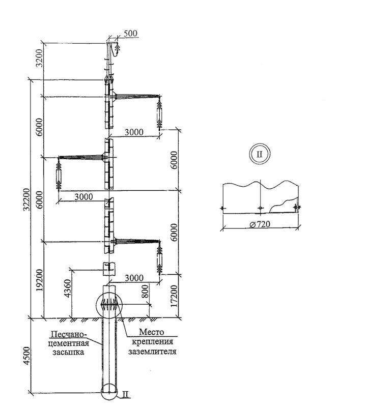
Types of poles for 220 kV lines
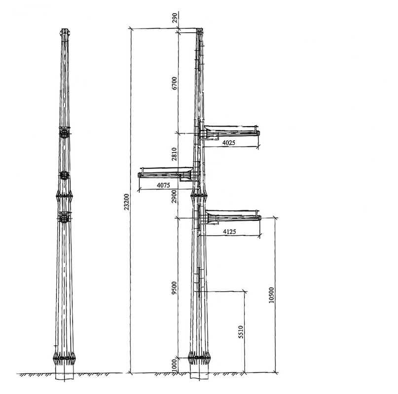
For 220 kV lines four types of single-circuit angle-anchor poles are normally developed: end; anchor; angle-anchor for a line angle of up to 60°; and angle-anchor for a line angle of up to 20°. They are made with one shaft, and the design allows them to be set on a foundation by flanges on the lower sections.
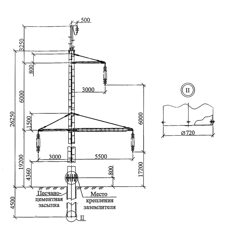
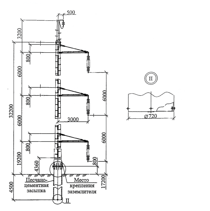
Single-circuit intermediate poles for 220 kV lines based on multi-sided shafts are developed in one of three versions:
- with the traditional conductor arrangement: one conductor at the top of the pole and two 6.0 m lower; for ordinary terrain such as fields and steppe;
- with a one-sided conductor arrangement: for terrain such as forests and for restricted conditions;
- with multi-sided crossarms: for urban conditions, with the option of servicing the poles from telescopic lift platforms.
The poles are set on a foundation in the form of a steel pipe joined to the lower section of the pole by flanges. The poles are designed to carry conductors AC 300/39 and AC 400/51; the earth wire is rope TK11.
Calculating the poles
The poles are calculated by the limit state method, whose main principles aim to ensure trouble-free operation of the structures, taking into account the variability of the properties of materials, of loads and actions, and of the geometry of structures and their working conditions. The limit states for which the poles, their foundations and bases are calculated are divided into two groups. The first includes states that lead to loss of load capacity of the elements or their complete unfitness for use, that is, failure of any kind: states at the greatest external loads and the lowest temperature, when the greatest bending or turning moments act on the poles and the greatest compressive or tensile forces on the poles and foundations. The second group includes states in which unacceptable deformation, displacement or deviation of the elements arises that breaches normal operation (the greatest deflection of the poles).
The method aims to prevent, with a certain probability, the first and second groups of limit states from occurring in service, and the first group from occurring during construction of the line. The requirements of the Rules for the Arrangement of Electrical Installations (PUE), 2026 edition, for earthing 220 kV poles are set out in the section below. When erecting poles, conductors and earth wires the general construction safety rules are followed. Recommendations on installation are in the knowledge base article on installing multi-sided poles.
Earthing of 220 kV poles under the PUE
Under the PUE (2026 edition), cl. 2.5.127, poles that carry an earth wire or other lightning protection devices should be earthed, as should poles with transformers, disconnectors, fuses or other apparatus. The resistance of the earthing device of a pole with an earth wire or other lightning protection devices must not exceed the values of Table 2.5.29, which depend on the equivalent soil resistivity ρ: up to 100 ohm·m — 10 ohms, above 100 to 500 — 15 ohms, above 500 to 1000 — 20 ohms, above 1000 to 5000 — 30 ohms, above 5000 — 6·10⁻³·ρ ohms.
These values apply to poles up to 50 m high; on taller poles the resistance must be half as much. On double-circuit and multi-circuit poles halving the resistance is recommended at any height. For poles with apparatus on lines of 110 kV and above, the resistance must not exceed the Table 2.5.29 value. For poles of mountain lines at an altitude above 700 m, the Table 2.5.29 values may be increased threefold. Where the line is protected by an earth wire, the resistance required for lightning protection must be ensured with the earth wire disconnected, and the resistance required for other purposes with the earth wire connected (cl. 2.5.127).
On poles of lines of 110 kV and above there must be at least two earthing conductors (down-leads); each must have a cross-section of at least 35 mm², and a single-wire conductor a diameter of at least 10 mm. Where the average annual relative humidity is 60 % or more, and in moderately and strongly aggressive environments, the conductors should be protected against corrosion at the point where they enter the soil (cl. 2.5.132).
Reinforced-concrete foundations of poles on lines of 110 kV and above may be used as natural earth electrodes if the anchor bolts are metallically bonded to the reinforcement and the concrete has no polymer waterproofing (cl. 2.5.128). An exception is reinforced-concrete poles and footings that limit the span of a crossing with a railway: their reinforcement must not be used as an earth electrode (cl. 2.5.211). In clay, loam, sandy-loam and similar soils with ρ ≤ 1000 ohm·m, the reinforcement of foundations and poles is used as natural earth electrodes, alone or together with artificial ones. In soils with ρ above 1000 ohm·m, the required resistance must be obtained with artificial earth electrodes only (cl. 2.5.129).
The acceptance test norms (cl. 1.8.202) provide for checking the earthing devices of a line: on all poles in populated areas, on sections with the most aggressive, landslide-prone, wind-eroded and poorly conducting soils and, in addition, on at least 2 % of all poles that have earth electrodes. The designer takes the final values for a specific line from the current text of the PUE.
When multi-sided poles are chosen for 220 kV lines
- urban and restricted conditions where a lattice pole needs a large footprint for its base;
- forests and narrow clearings: one-sided conductor arrangement reduces the route width;
- obstacle crossings and line reconstruction that need fast installation with compact sections;
- difficult turning and terminal sections where new-generation angle tension poles are used.
What is needed for calculation and ordering
Send the line data: number of circuits, conductor and earth wire type, route diagram with angles, wind and ice region, soil conditions. We propose the type of poles and foundations and calculate the price and lead time. You can fill in the technical specification form for a power line pole.
Updated:
220 kV line poles: frequently asked questions
How many types of angle-anchor poles are developed for 220 kV lines?
Four: end, anchor, angle-anchor for a turn up to 60°, and angle-anchor for a turn up to 20°.
What conductor grades do these poles carry?
AC 300/39 and AC 400/51; the earth wire is rope TK11.
In what conditions can multi-sided 220 kV poles be used?
In wind and ice regions I–IV, in unpopulated and populated areas, and in mildly and moderately aggressive environments.
How do intermediate poles with multi-sided crossarms differ from the other versions?
They are meant for urban conditions and allow poles to be serviced from telescopic lift platforms — unlike the traditional or one-sided conductor arrangements meant for open terrain.
Questionnaire: technical assignment form
Fill in the form and email it to us: we will prepare the KM-stage design documentation from it and calculate the price. The PDF is handy to print; the DOCX can be filled in on a computer.
Technical assignment form: overhead line pole
A questionnaire for preparing KM-stage design documentation for a steel polygonal overhead line pole: operating conditions, conductors, earth wires, insulator strings, clearances.
Related products: Overhead power line masts · Substation gantries
More on this topic: Typical Lattice Power Line Poles: Classification and Checks · Typical Lattice Transmission Poles 35–750 kV · Steel Multi-sided Poles for 6–10 kV Lines · Power Line Pole Types by Purpose: Suspension, Tension, Angle, Terminal · Power Line Protection Zone: Widths by Voltage Class · Distance Between Power Line Poles: What Determines the Span Length
Get a quote for your requirements
Send us your requirements — we will calculate the price and lead time.