
Home / Products / Overhead power line masts / Steel Multi-sided Poles for 6–10 kV Lines
Overhead power line masts
Steel Multi-sided Poles for 6–10 kV Lines
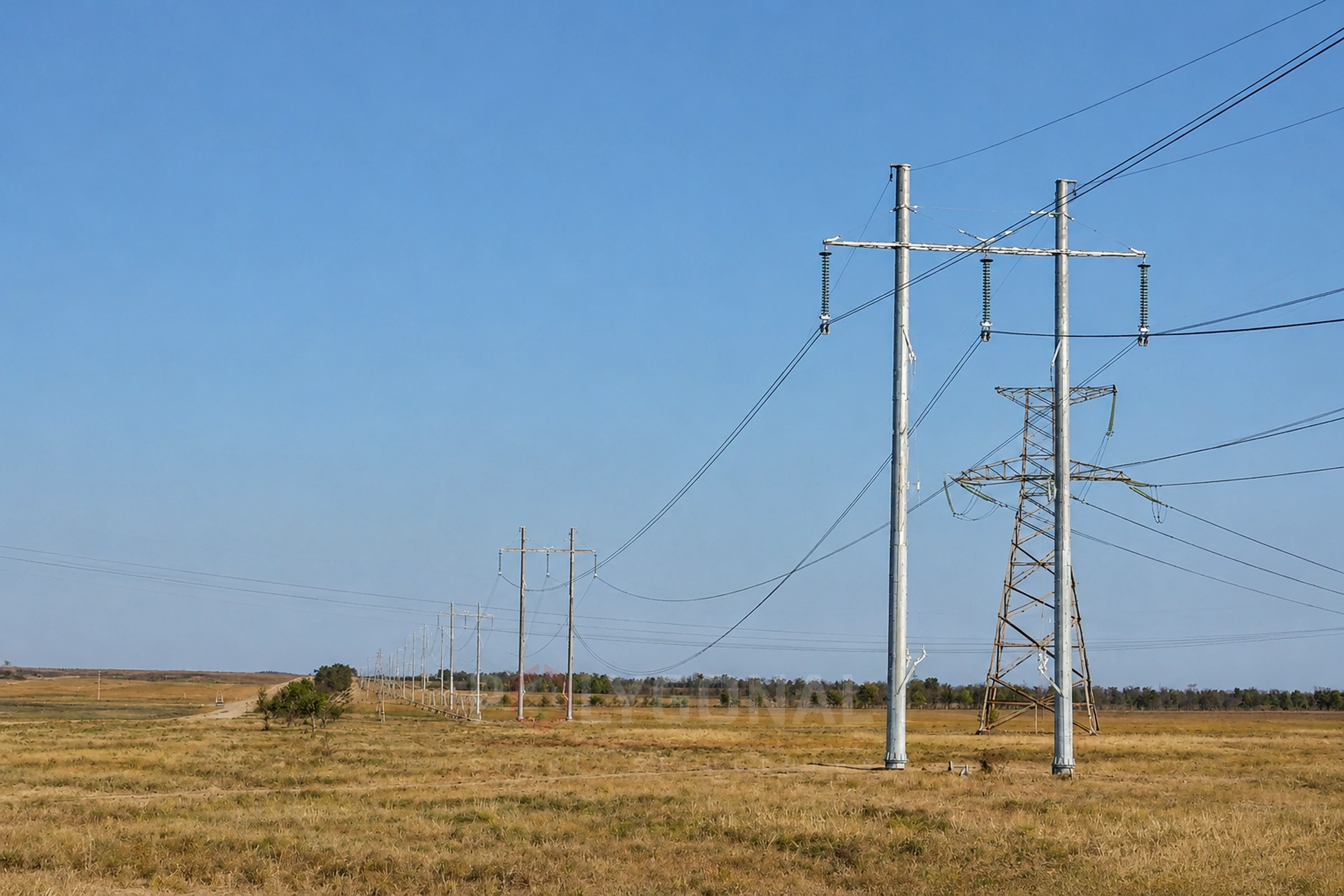
Single-shaft steel multi-sided poles for 6–10 kV overhead lines: types of poles, conductors and insulators, the region of use and the calculation principles.
Contents
Types of poles for 6–10 kV lines
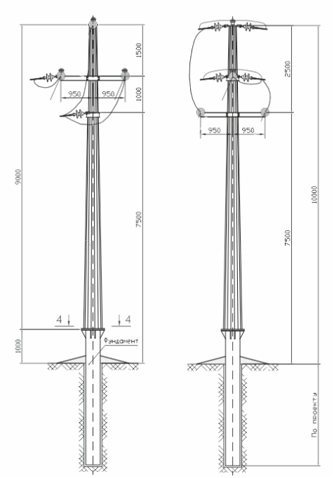
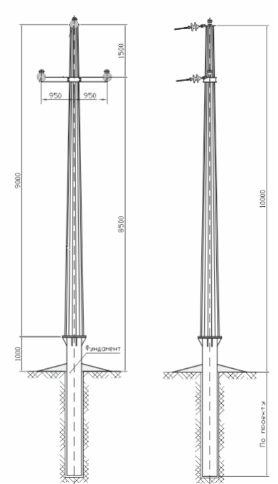
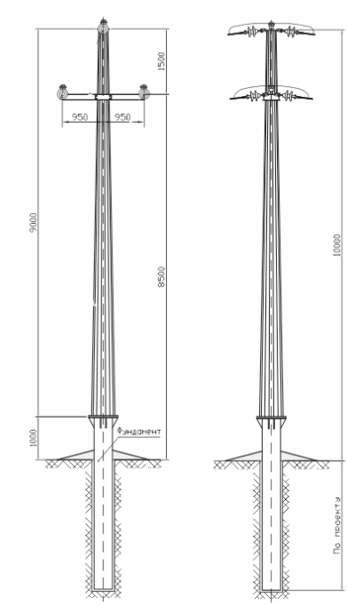
We prepare KM drawings and manufacture single-circuit steel multi-sided poles for overhead power lines of 6–10 kV. All designs are single-shaft, on steel multi-sided shafts with a flange connection to the foundation; the foundation is a pipe with a flange.
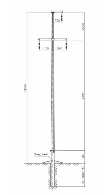
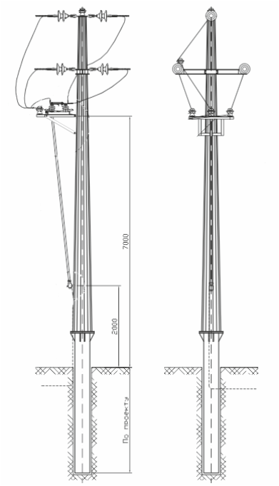
The types of pole are: intermediate; branch anchor; angle-anchor; anchor with disconnector; anchor with cable joint. For crossing obstacles, including roads, we design transition poles of anchor and intermediate type. When crossing a line of higher voltage, we design lowered poles to keep the required clearances between the conductors.
Scope of application
The poles are made to carry steel-aluminium conductors AC 50/8, AC 70/11, AC 95/16 and AC 120/19 and self-supporting insulated conductors of the SIP-3 (SAX) type with a nominal conductor cross-section of 50 to 150 mm². They are designed for glass suspension insulators PS70E or polymer LK70/10 and pin insulators ShF-20V and ShK-10.
The poles are used in wind regions I–III and ice regions I–III, in populated and unpopulated areas, and in regions with atmospheric pollution levels 1 to 4 with both glass and polymer insulation. Intermediate poles are designed for suspension insulation (the most reliable), the other types for strain insulation.
The angle-anchor pole is designed for a line angle of up to 60° and withstands the breaking of any two conductors; the tension of the conductors erected in one span with those in the other not erected, at the maximum permitted line angle, must not exceed 2/3 of the maximum tension. In the final state the pole withstands the erection forces while three conductors are tensioned. The distance between anchor poles on lines up to 20 kV with suspension insulators must not exceed 3 km, and on lines with pin insulators in ice regions 1–3 it must not exceed 1.5 km (PUE (2026 edition), cl. 2.5.135).
Overhead power line masts
Earthing of 6–10 kV pole lines under the PUE
The Rules for the Arrangement of Electrical Installations (PUE), 2026 edition (cl. 2.5.127), require reinforced concrete and metal poles of 3–35 kV lines to be earthed, as well as poles that carry power or instrument transformers, disconnectors, fuses or other apparatus. For a steel 6–10 kV pole the earthing is part of the line design, and the resistance needed depends on the soil and the terrain.
Where a 3–20 kV line runs through a populated area, and for poles that bound the span of a crossing with engineering structures (other lines, pipelines and the like), a limit is set on the resistance of the earthing arrangement: it must not exceed the values of Table 2.5.29. The values depend on the equivalent soil resistivity ρ: 10 Ω up to 100 Ω·m, 15 Ω above 100 up to 500, 20 Ω above 500 up to 1000, 30 Ω above 1000 up to 5000; for soils above 5000 Ω·m the table gives a formula. The required resistance must be achieved with artificial earth electrodes; there is no need to take the natural conductivity of the foundations and underground parts of the poles into account in the calculation (cl. 2.5.130).
In unpopulated areas no limit is set on the earthing resistance of poles on 3–20 kV lines, except for poles that bound a crossing span (for them the same Table 2.5.29 applies). On 6–10 kV lines in unpopulated areas, the natural conductivity of the reinforced concrete foundations and the underground part of the poles in soils with ρ up to 1000 Ω·m may be used as a natural earth electrode with no limit on its resistance; for reinforced concrete poles, provided the bars of the longitudinal reinforcement in the underground part of the shafts, the earthing conductors and the artificial earth electrode (if there is one) are metallically bonded (cl. 2.5.127, 2.5.130). In soils with a higher ρ the poles must also have artificial earth electrodes with a resistance of no more than 500 Ω.
On a pole with apparatus, the earthing resistance on 3–35 kV lines must not exceed 10 Ω, unless the technical conditions or the operating manual of the equipment require otherwise. These are requirements for the line design; the designer takes the final values for a specific object from the current text of the PUE. More on earthing: grounding of metal lighting and 0.4–10 kV line poles.
Calculating the poles
The loads on a pole from the conductors are calculated for normal and emergency modes. The poles are calculated by the limit state method, the one the PUE (2026 edition), cl. 2.5.25, adopts for poles and foundations of overhead lines: the strength and the overall and local stability of the elements of bent multi-sided section are checked. The section of the shafts is chosen from the permissible stresses in the metal, the size of the polygon side and the stability of the shell; the check is made for all combinations of wind and ice regions and conductor grades for which the pole is designed.
Steel multi-sided poles have become widespread in overhead line construction for a number of objective reasons. Unlike standard power line poles, multi-sided ones are designed to suit the features of the particular line. We produce KMD drawings in 3D mode, which rules out mechanical errors.
Overhead power line masts
Multi-sided or reinforced concrete poles: a comparison
| Criterion | Reinforced concrete pole | Steel multi-sided pole |
|---|---|---|
| Weight and transport | heavy, special equipment needed | lighter, the shaft is assembled from sections |
| Installation | set in a pit, large equipment required | flange on a foundation or set in a drilled pit |
| Resistance to corrosion and vandalism | depends on concrete and reinforcement | hot-dip galvanising to DSTU EN ISO 1461:2024, closed profile |
| Look in urban areas | massive | compact, aesthetic |
| Adaptation to the line | standard solutions | designed for the specific line conditions |
When to choose steel multi-sided poles for 6–10 kV
- a narrow right-of-way, urban and suburban areas that need compact poles;
- complex routes, turns, branches and crossing of obstacles (roads, railways, other lines);
- fast construction or reconstruction of lines: the pole can be installed without heavy equipment;
- conditions requiring durability and resistance to wind, ice and vandalism.
What is needed for calculation and ordering
Send the line voltage, conductor type and cross-section, the route diagram with angles and branches, the wind and ice region and the type of insulation. You can also fill in the technical specification form for a power line pole. We propose pole types and calculate the price and lead time.
Updated:
Poles for 6–10 kV lines: frequently asked questions
What is the maximum turning angle for a 6–10 kV angle-anchor pole?
Up to 60°; the pole also withstands the breaking of any two conductors.
What is the maximum distance between anchor poles?
No more than 3 km on lines with suspension insulators; on lines with pin insulators in ice regions 1–3, no more than 1.5 km (PUE (2026 edition), cl. 2.5.135).
What conductors are these poles designed for?
Steel-aluminium conductors AC 50/8 to AC 120/19 and self-supporting insulated conductors SIP-3 (SAX) with a 50–150 mm² cross-section.
Can a 6–10 kV pole be installed where the line crosses a higher-voltage line?
Yes, for such cases we design lowered poles to keep the required clearances between the conductors of both lines.
How does a single-shaft 6–10 kV pole differ from poles for higher voltage?
It’s single-shaft (not built from several shafts), designed for a smaller conductor cross-section, and rated for smaller wind and ice regions (I–III instead of I–V), so it’s structurally lighter.
Questionnaire: technical assignment form
Fill in the form and email it to us: we will prepare the KM-stage design documentation from it and calculate the price. The PDF is handy to print; the DOCX can be filled in on a computer.
Technical assignment form: overhead line pole
A questionnaire for preparing KM-stage design documentation for a steel polygonal overhead line pole: operating conditions, conductors, earth wires, insulator strings, clearances.
Related products: Overhead power line masts · Overhead line fittings and crossarms (0.4-10 kV)
More on this topic: Typical Lattice Power Line Poles: Classification and Checks · Typical Lattice Transmission Poles 35–750 kV · Power Line Pole Types by Purpose: Suspension, Tension, Angle, Terminal · Power Line Protection Zone: Widths by Voltage Class · Distance Between Power Line Poles: What Determines the Span Length · Steel Multi-sided Poles for 35 kV Lines
See also: Catalogue of Fittings for 0.4–10 kV Overhead Lines · Earthing of Overhead Line Poles above 1 kV under PUE
Get a quote for your requirements
Send us your requirements — we will calculate the price and lead time.