
Home / Products / Overhead power line masts / Steel Multi-sided Poles for 110 kV Lines
Overhead power line masts
Steel Multi-sided Poles for 110 kV Lines
The types of multi-sided poles for 110 kV lines, features of their manufacture and their scope of application.
Contents
Types of poles for 110 kV lines
POLYGONAL prepares KM drawings and manufactures steel multi-sided poles for 110 kV overhead power lines. If you supply the KM drawings, we will quickly prepare the KMD and release them to production. The power line poles are made by modern technology.
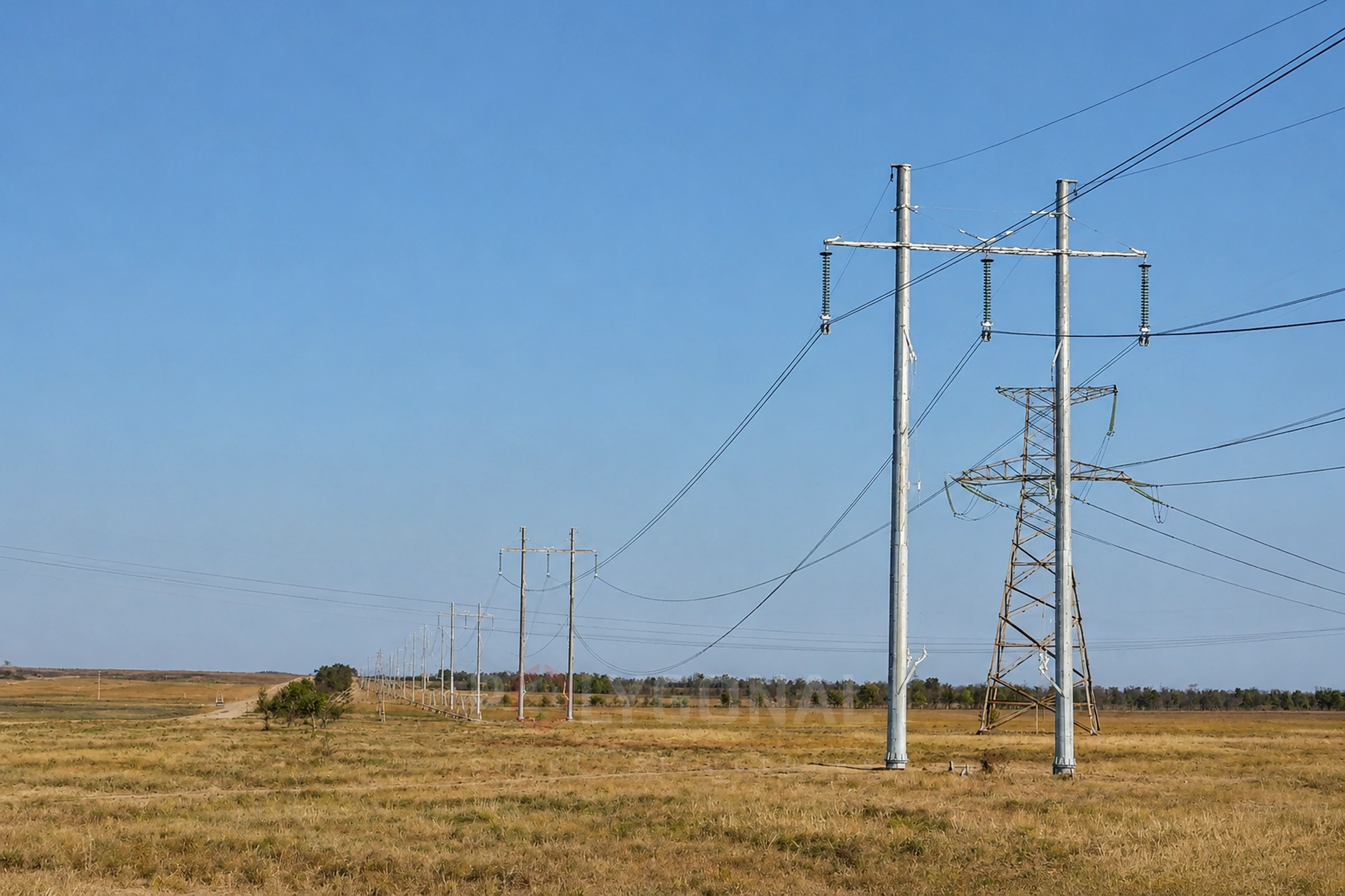
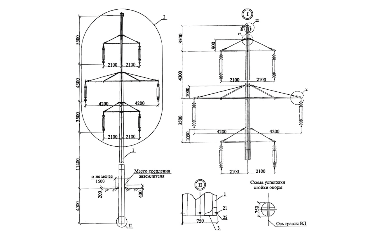
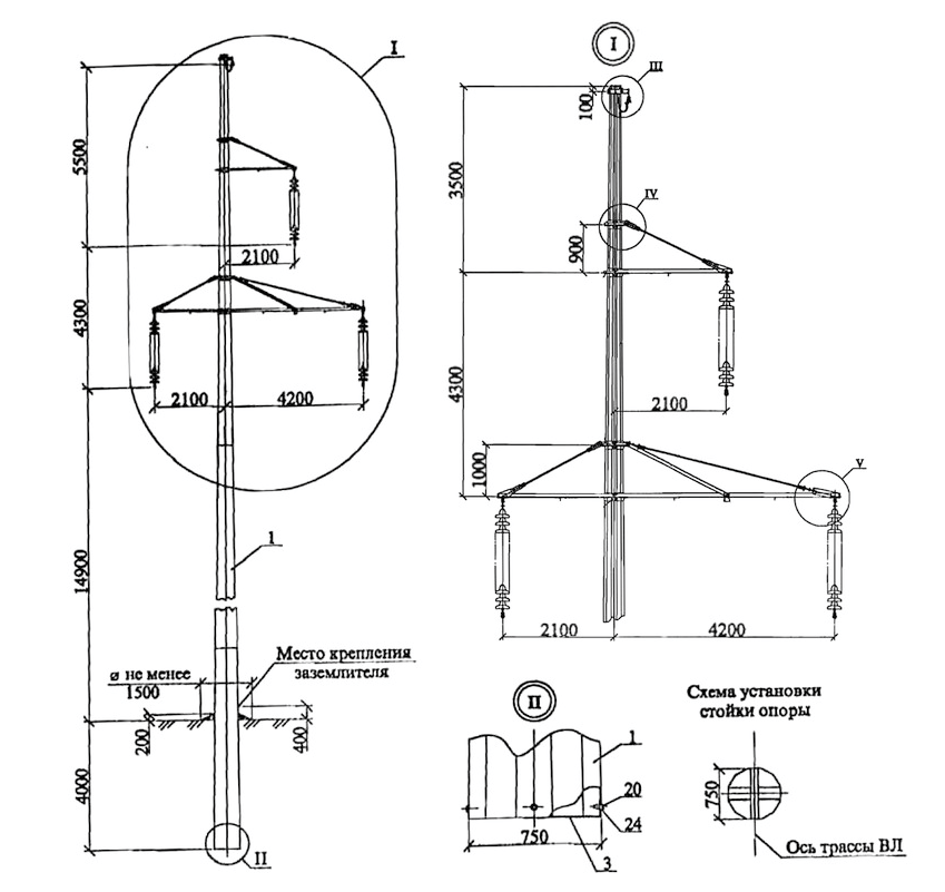
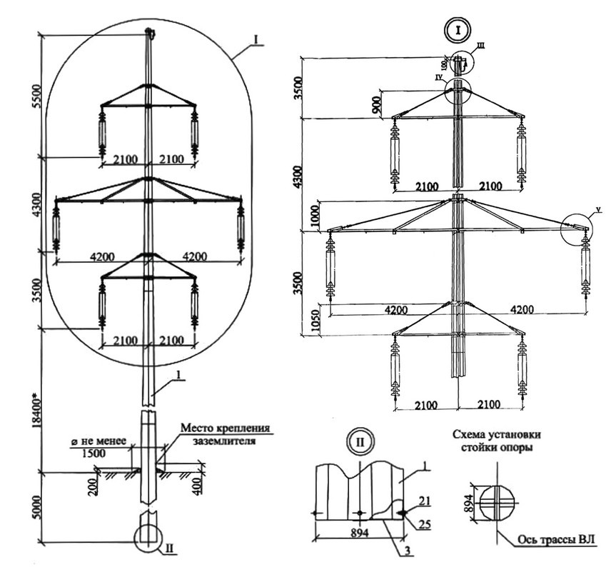
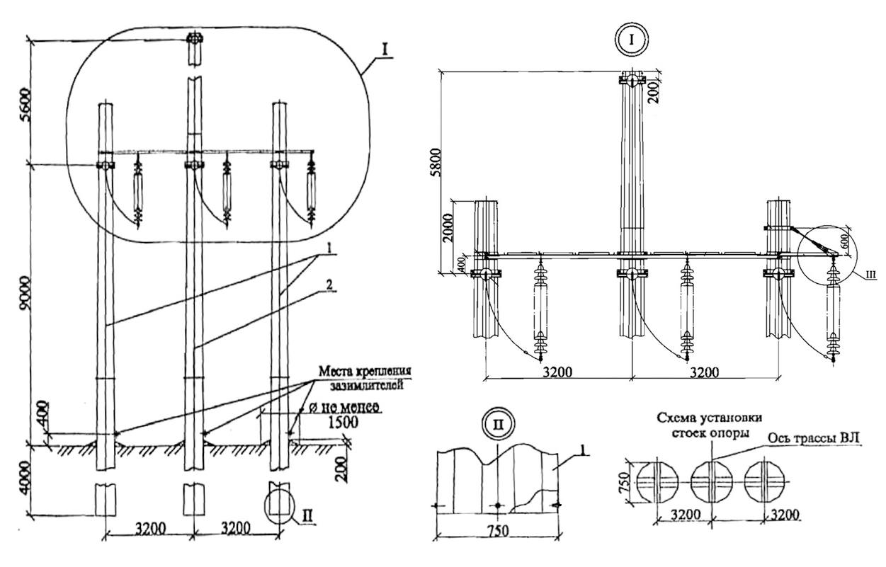
Single- and double-circuit intermediate poles are used to carry steel-aluminium conductors up to AC 240/32. All poles are regular twelve-sided polygons in section. Intermediate poles are set in drilled pits to a depth of 4.0 m; a version with a flanged fixing to a foundation is also possible. The steel shafts are assembled from several sections with a slip joint. The single-circuit anchor and angle-anchor poles are made with three shafts and a rigid tie, fixed in a drilled pit to a depth of 4.0 m or by flanges; a single-shaft pole can be designed for special conditions. The shafts of anchor poles are also assembled with a slip joint.
We make single-circuit intermediate, double-circuit intermediate, raised double-circuit intermediate and anchor poles. Climbing is recommended from telescopic lift platforms, with stock ladders or with special stock lifting devices; fixed ladders are provided for climbing above the lower crossarm, and if wished the whole shaft can be equipped with them.
Manufacture
The steel structures are made to technical conditions agreed with the authors of the design. All elements of the poles are designed to meet the requirements for articles to be hot-dip galvanised to DSTU EN ISO 1461:2024. The surface of the bent shafts, 4.5 m from the butt, has a bitumen coating at least 3 mm thick or another insulating coating.
The shafts are fitted with top caps and stiffening diaphragms at the butt, which also serve as bearing elements for the pole in the ground. The lower and middle sections of the shafts have stiffening diaphragms at the top to prevent the slip joint from being crushed while the pole works under design loads.
Overhead power line masts
Scope of application
Steel poles for 110 kV lines are meant for use in wind regions I–V and ice regions I–IV, in populated and unpopulated areas. The angle-anchor pole allows a maximum line angle of 45°.
The fixing in the ground of intermediate and anchor poles is normally made without a crossbar in a drilled pit 4 m deep; where needed a crossbar is fitted by calculation. The pits are backfilled with a sand-gravel or sand-cement mixture. Earthing follows the Rules for the Arrangement of Electrical Installations (PUE), 2026 edition; the main requirements are in the next section.
Finished elements must be slung in ways that leave no permanent deformation, dents or damage to the galvanised coating; shafts are stacked on wooden supports. When erecting poles, conductors and earth wires the general construction safety rules are followed.
Earthing of 110 kV pole lines under the PUE
Under the Rules for the Arrangement of Electrical Installations (PUE), 2026 edition, poles that carry an earth wire or other lightning protection are to be earthed. The resistance of their earthing device must not exceed the values of Table 2.5.29 for poles up to 50 m high, and for poles over 50 m it must be half of them. The table gives 10 ohm for equivalent soil resistivity ρ up to 100 ohm·m, 15 ohm for ρ over 100 up to 500, 20 ohm for ρ over 500 up to 1000, 30 ohm for ρ over 1000 up to 5000 and 0.006·ρ ohm for ρ over 5000. On double-circuit and multi-circuit poles, halving the resistance is recommended at any height. For mountain lines at more than 700 m above sea level the values of Table 2.5.29 may be tripled. On lines protected by an earth wire, the resistance set by lightning-protection conditions must be reached with the wire disconnected, and the resistance set by other conditions with the wire not disconnected (cl. 2.5.127).
Reinforced-concrete pole foundations may serve as natural earth electrodes if the anchor bolts are metallically bonded to the reinforcement and the concrete has no polymer waterproofing (cl. 2.5.128). There are two exceptions. At a railway crossing, the reinforcement of reinforced-concrete poles and pole stubs that bound the crossing span may not be used as an earth electrode (cl. 2.5.211). The other depends on the soil: in clayey, loamy, sandy-loam and similar soils with ρ ≤ 1000 ohm·m the reinforcement of foundations and poles is used as a natural earth electrode, either with no extra electrodes or together with artificial ones, while in soils with ρ > 1000 ohm·m the required resistance must be reached with artificial earth electrodes alone (cl. 2.5.129).
A 110 kV pole needs at least two earthing conductors (down leads), each with a cross-section of at least 35 mm² and, for single-wire conductors, a diameter of at least 10 mm (cl. 2.5.132). Earth electrodes are normally laid at least 0.5 m deep, and 1 m deep in ploughed land (cl. 2.5.133). These are requirements for the line design: the designer takes the final values for a particular line from the current text of the PUE.
Why these poles beat the alternatives
A twelve-sided closed profile can be fully hot-dip galvanised, while lattice poles often contain lap-welded joints without a closed seam, which galvanising rules do not allow — this gives multi-sided poles a longer service life than lattice or reinforced-concrete alternatives. See Transmission Poles: Multi-Sided, Lattice or Reinforced Concrete for details.
Unloading on site
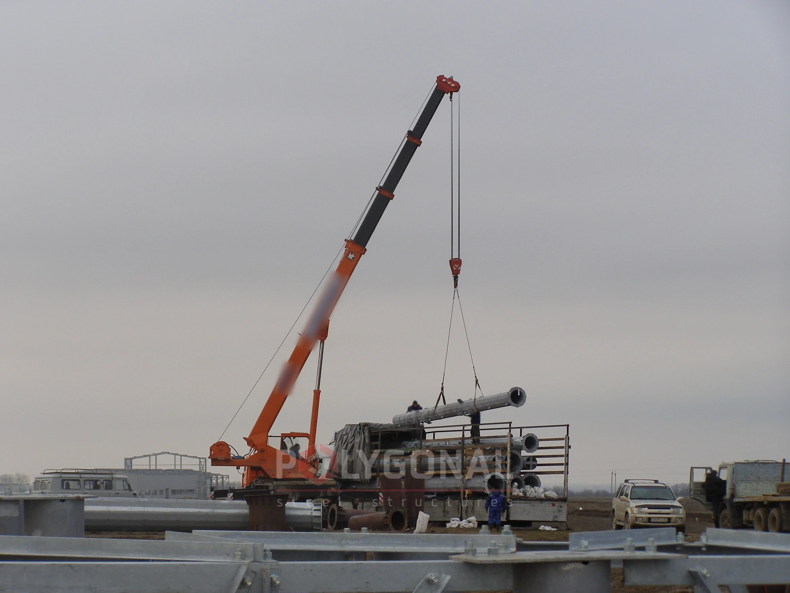
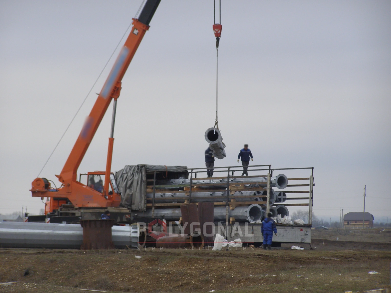
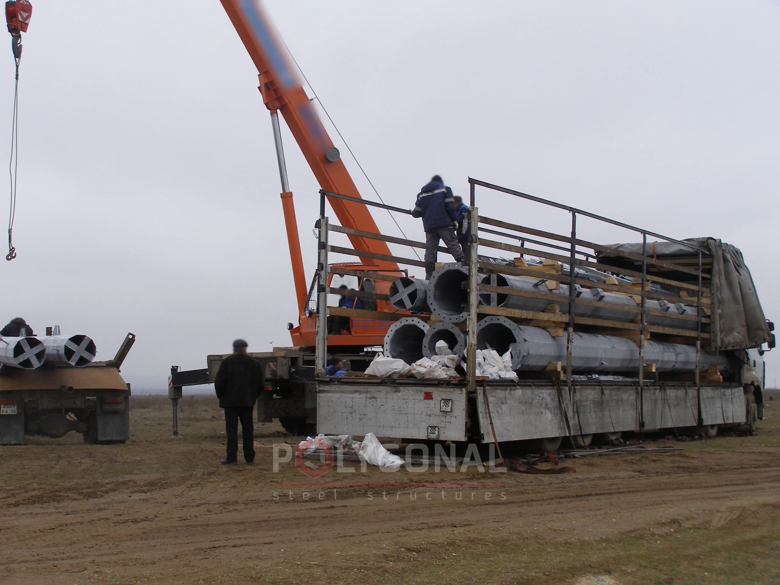
Unloading multi-sided 110 kV overhead line poles with a truck crane at the construction site.
Suspension and tension poles: how the roles are split
Suspension poles only support the conductors and earth wires on straight sections of the route; they make up most of a line. Tension poles take the difference in conductor tension: they are used at obstacle crossings, where the conductor type or cross-section changes, and at angles; angle tension poles are designed for a specific route angle.
For 110 kV we make single-circuit suspension, double-circuit suspension, raised double-circuit suspension and tension poles; the design is chosen for the specific line project.
What is needed for calculation and ordering
Send the line data: number of circuits, conductor type and cross-section, route diagram with angles, wind and ice region, soil conditions. If you have KM drawings we will prepare KMD; if not, we will develop KM. You can also fill in the technical specification form for a power line pole.
Updated:
Poles for 110 kV lines: frequently asked questions
How deep is a 110 kV line pole set?
In a drilled pit 4.0 m deep; a version with a flanged fixing to a foundation is also available.
What is the maximum turning angle for a 110 kV angle-anchor pole?
45°.
What shape is the 110 kV pole shaft?
A regular twelve-sided polygon.
What conductors are these poles designed for?
Steel-aluminium conductors up to AC 240/32 in cross-section.
Can a 110 kV pole be made with a single shaft?
Yes, for special conditions a version with a single shaft instead of three shafts with a rigid tie is available.
Questionnaire: technical assignment form
Fill in the form and email it to us: we will prepare the KM-stage design documentation from it and calculate the price. The PDF is handy to print; the DOCX can be filled in on a computer.
Technical assignment form: overhead line pole
A questionnaire for preparing KM-stage design documentation for a steel polygonal overhead line pole: operating conditions, conductors, earth wires, insulator strings, clearances.
Related products: Overhead power line masts · Substation gantries
More on this topic: Typical Lattice Power Line Poles: Classification and Checks · Typical Lattice Transmission Poles 35–750 kV · Steel Multi-sided Poles for 6–10 kV Lines · Power Line Pole Types by Purpose: Suspension, Tension, Angle, Terminal · Power Line Protection Zone: Widths by Voltage Class · Distance Between Power Line Poles: What Determines the Span Length
Get a quote for your requirements
Send us your requirements — we will calculate the price and lead time.