
Home / Products / Substation gantries / Protective Structures for Substation Switchyard Equipment
Substation gantries
Protective Structures for Substation Switchyard Equipment
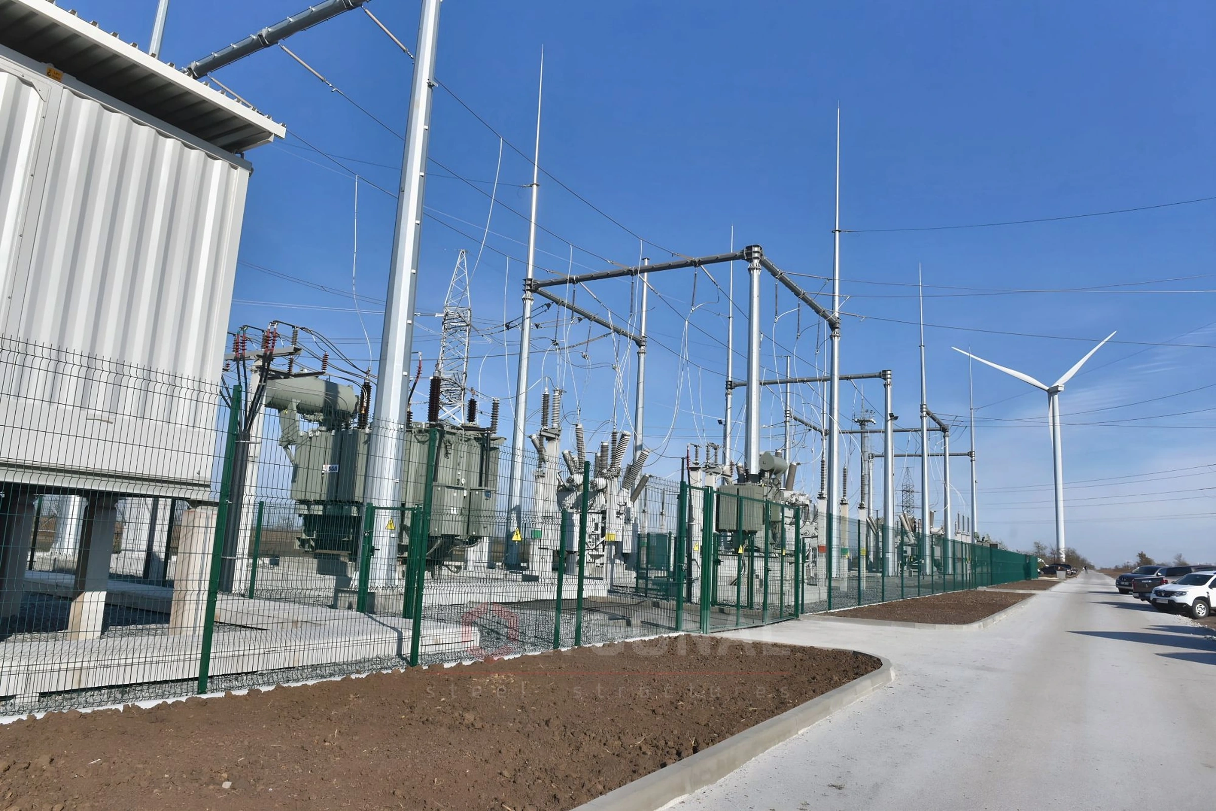
Besides switchyard portals, we design and manufacture protective structures for open switchyard (ORU) equipment at substations — for extra protection of critical equipment.
Contents
- What we design and manufacture
- Materials and manufacturing
- How to order
- What data the design needs and why
- Coatings: galvanising and fire protection
- What to allow for in drawings and coatings
- What the PUE require of a switchyard: loads, heating, safety margins
- C245 or C345 steel: what the higher grade changes
- Checklist before ordering
- Common mistakes
What we design and manufacture
Protective structures for substation switchyard equipment — transformers and other critical equipment. Every project is designed individually for the specific facility and the type and placement of the equipment to be protected: there are no standard sizes.
Materials and manufacturing
Load-bearing elements are made of C245 and C345 steel (DSTU 8539:2015), with anti-corrosion protection and fire-resistant coating — using the same methods and production facilities as our other steel structures.
How to order
Send the substation’s parameters and details of the equipment to be protected (type, placement, dimensions), the voltage class and the region. We will prepare an individual design and calculation.
What data the design needs and why
The more complete the input data, the more accurate the calculation and the fewer follow-up questions. Below is what to send and what it is used for in the design; leave blank whatever you do not know and we will clarify it.
| Data | What it is needed for | What to send |
|---|---|---|
| Equipment to be protected | Sets the dimensions and the zone that must be covered | The equipment’s dimensional drawing or on-site measurements |
| Placement in the switchyard | Determines clearances to neighbouring structures and access routes | A layout drawing or a plan with dimensioned positions |
| Voltage class | The minimum clearances to live parts depend on it (PUE rules) | The voltage class and a list of live parts nearby |
| Underground part | Foundations must not clash with cable trenches, the earthing grid or existing foundations | A plan of underground services; soil data, if available |
| Construction region | Sets wind and ice loads under DBN V.1.2-2:2006 | The town or region, see [wind regions](/en/products/lighting-columns/ukraine-wind-regions-pole-calculation/) |
| Coating requirements | Determine corrosion protection and any need for fire protection | Design requirements and the fire resistance class, if specified |
You can send the data in any form; the request procedure is described in How to order poles and masts.
Coatings: galvanising and fire protection
The minimum zinc thickness under DSTU EN ISO 1461:2024 depends on the steel thickness of each element, not of the structure as a whole:
| Steel thickness, mm | Minimum local, µm | Minimum mean, µm |
|---|---|---|
| > 6 | 70 | 85 |
| > 3 – ≤ 6 | 55 | 70 |
| ≥ 1.5 – ≤ 3 | 45 | 55 |
| < 1.5 | 35 | 45 |
Example: an element with a 4 mm wall falls in the > 3 – ≤ 6 row, so the local thickness of the coating (the mean of several readings on a reference area) must be at least 55 µm and the mean over all areas at least 70 µm. More in Zinc coating thickness.
What to allow for in drawings and coatings
- closed cavities need vent and drain holes: liquid trapped in a sealed volume boils in the molten zinc. The holes are put into the drawings before fabrication, see Designing for hot-dip galvanising;
- an assembly should ideally fit into the 13,000 × 1,600 × 3,200 mm bath; if it does not, it is split into parts that are joined on site or, by separate agreement, dipped in two stages;
- a fire-resistant coating on zinc is, as a rule, applied over a compatible primer approved by the maker of the fire-protection product (or under the maker’s approved surface-preparation scheme); if you plan one, tell us before galvanising, because surface preparation is agreed separately;
- the fire resistance of load-bearing structures (the load-bearing capacity criterion) is denoted by the letter R and minutes (R30, R60, R90, R120) under DSTU EN 13501-2:2023; whether it is required, and which class, is set by the facility design;
- uncoated areas of up to 10 cm² each, no more than 0.5% of the surface in total, are repaired with zinc-rich paint or zinc spraying; coating damage caused during erection must also be restored.
What the PUE require of a switchyard: loads, heating, safety margins
Chapter 4.2 of the Rules for the Arrangement of Electrical Installations (PUE), 2026 edition, applies to stationary switchgear, substations and distribution points of AC above 1 kV, new and reconstructed; it covers special substations (mobile, traction, underground) only in part (cl. 4.2.1). This is what it requires of the structures of an open switchyard (ORU), and of the busbars and insulation on them:
| Topic | What the PUE require | Clause, PUE (2026 edition) |
|---|---|---|
| Loads | Structures that carry equipment, apparatus, live parts and insulators must be designed for loads from weight, tension, switching operations, wind, ice, short circuits and seismic effects; steel structures must have an anti-corrosion coating | 4.2.14 |
| Heating | Building structures near live parts must not be heated by the current to more than 50 °C where electrical personnel can touch them, or to more than 70 °C where they cannot be touched. If the AC in the live parts near the structures does not exceed 1000 A, the structures may be left unchecked for heating | 4.2.14 |
| Climate | Mechanical loads from wind and ice on busbars and structures, and the design air temperatures, must be determined from the climatic zoning maps and the chapter 2.5 requirements for overhead lines, depending on the reliability class; the ORU voltage shows which overhead-line class the installation corresponds to | 4.2.46 |
| A person with tools | For the second group of limit states, the mass of a person with tools and erection devices must also be taken into account where tension insulator strings (2.0 kN), suspension insulator strings (1.5 kN) or post insulators (1.0 kN) are used | 4.2.46 |
| Safety factor | For the loads of cl. 4.2.46 the safety factor must be taken as not less than 3 for flexible busbars (against ultimate tensile strength), not less than 4 for insulator strings (against the guaranteed minimum breaking load of the whole insulator), and not less than 3 for the coupling fittings of flexible busbars (against minimum breaking load) | 4.2.47 |
| Special conditions | Where the air may contain substances that impair insulation or have a destructive effect on equipment and busbars, protective measures must be taken (cl. 4.2.18); at altitudes above 1000 m a.s.l. air insulation gaps and insulation must be selected with corrections for the lower atmospheric pressure (cl. 4.2.20) | 4.2.18, 4.2.20 |
| Lines on structures | It is prohibited to run overhead lighting, communication and signalling lines over or under the live parts of an ORU, or to use substation structures with lightning rods for overhead lines of any kind | 4.2.61 |
These are requirements for the ORU design; for a specific facility the designer takes the final values from the current text of the PUE.
C245 or C345 steel: what the higher grade changes
Load-bearing elements are made from both grades (DSTU 8539:2015). The number in the designation is the yield strength in MPa (the exact standard value depends on the thickness of the rolled product). Moving to C345 reduces the cross-section only where strength governs the size of the element.
A simplified example without safety factors: a bar carries an axial tensile force of 490 kN. The required area in C245 steel is 490,000 N / 245 MPa = 2,000 mm², in C345 steel — 490,000 / 345 ≈ 1,420 mm². The difference is 580 mm², or 29% (245 / 345 ≈ 0.71).
| What governs the element size | What C345 gives |
|---|---|
| Strength | The cross-section can be reduced, by 29% in the example |
| Deflection and stiffness | Nothing: the elastic modulus of steels is practically the same |
| Stability of slender bars | Mostly nothing: Euler’s critical load depends on the elastic modulus and the geometry |
| Galvanising | The steel composition (silicon, phosphorus) affects the coating, so the grade is agreed in advance with the galvanising plant |
The grade is fixed in the calculation; the methods are described in Calculation methods.
Checklist before ordering
- a dimensional drawing or measurements of the equipment are available;
- a switchyard layout drawing with the position marked is available;
- the voltage class and the distances to neighbouring live parts are known;
- underground services and existing foundations have been checked on site;
- the construction region is determined;
- it is decided whether painting and fire protection are needed, and which R class;
- it is considered how the equipment is serviced and replaced, so that the structure does not block access;
- erection is planned: it is carried out by a specialised organisation, and the conditions of work in a live switchyard are agreed by the customer.
Common mistakes
- dimensions are taken by eye, without measuring on site;
- clearances to live parts and access for replacing the equipment are not checked;
- vent holes are forgotten, and the structure cannot be galvanised properly;
- a fire-resistant coating is applied to zinc without a primer or surface preparation approved by the maker of the product, and it may peel off;
- C345 is chosen to save metal although stiffness or stability governs the element size.
Updated:
Protective structures for switchyard equipment: frequently asked questions
Are there standard sizes for switchyard protective structures?
No, every project is designed individually for the specific equipment and substation.
What are the protective structures made of?
The load-bearing elements are made of C245 and C345 steel to DSTU 8539:2015, with anti-corrosion protection and a fire-resistant coating.
Can you design protection for a specific transformer or other equipment?
Yes, send us the equipment and substation parameters and we will prepare an individual design.
How much does galvanising such a structure cost?
Galvanising is charged by mass: 20–38 UAH per kg including VAT, approximately, as of September 2026. For a notional 5 t that is 100,000–190,000 UAH (5,000 × 20 and 5,000 × 38). We name the price of the structure after the calculation; galvanising can be estimated in the calculator.
Can a structure made of hollow elements be galvanised?
Yes, if the closed cavities have vent and drain holes. It is better to put them into the drawings before fabrication: reworking a finished product costs more.
Is fire protection needed, and of which class?
The substation design sets this under fire safety requirements. If there is a requirement, state the R class (R30, R60, R90, R120) in your request: it determines which coating is needed and of what thickness.
What if the exact dimensions of the equipment are not available?
Send photos and the equipment’s data plate details, or measure on site. The dimensions determine the structure, so without them the calculation can only be approximate.
Related products: Substation gantries
More on this topic: Typical Substation Gantries 35–500 kV · Multi-sided Substation Gantries: Design and Foundations · Multi-Sided Switchyard Gantries 35–150 kV: Sizes, Heights, Bays · Installing a Substation Gantry: Slinging, Setting the Shafts and Crossbeam, Tightening the Bolts · What Is a Substation Gantry: Purpose and Voltage Classes · Restoring Damaged Substation Switchyard Portals
Get a quote for your requirements
Send us your requirements — we will calculate the price and lead time.