
Home / Products / Substation gantries / Multi-Sided Switchyard Gantries 35–150 kV: Sizes, Heights, Bays
Substation gantries
Multi-Sided Switchyard Gantries 35–150 kV: Sizes, Heights, Bays
The sizes of multi-sided switchyard gantries for 35 and 110 kV: marks, heights to the crossarm and ground-wire post, bay lengths, and the numbers of ground-wire posts and lightning rods. 150 kV gantries are covered separately.
Contents
The multi-sided gantry series
Multi-sided switchyard gantries are made of bent steel posts with a multi-sided section. How they beat the typical lattice gantries is explained in Polygonal Switchyard Portals: Advantages over Typical Designs, Design of Portals and Foundations.
Below are the series for 35 and 110 kV substations: ПС-35…-Б (6 marks) and ПС-110…-Б (13 marks); in Latin letters they read PS-35…-B and PS-110…-B, while on the drawings the marks are written in Cyrillic. For each mark the table gives the height to the crossarm and to the ground-wire post, the bay length, and the numbers of bays, ground-wire posts and lightning rods. 150 kV gantries have a catalogue of their own; see the section “150 kV gantries”.
Polygonal switchyard portals for 35 kV: the ПС-35…-Б series
The ПС-35…-Б series has six marks: ПС-35Ш-Б and five portals from ПС-35Я1-Б to ПС-35Я5-Б. The designations repeat those of the typical ПС-35Ш and ПС-35Я1–Я5 portals (listed in Typical Switchyard Portals 35–500 kV), but the posts here are polygonal.
Five of the six marks have a height to the crossarm of 7.85 m and a 6 m bay; ПС-35Ш-Б is lower (6.1 m) with a 2 m bay. Where a ground-wire post is fitted, it stands 3 m above the crossarm (10.85 m) and the lightning rod rises another 5 m, so the overall height of those portals is 15.85 m.
| Mark | Height to crossarm, m | Height to ground-wire post, m | Overall height, m | Bay length, m | Number of bays | Number of ground-wire posts | Number of lightning rods |
|---|---|---|---|---|---|---|---|
| ПС-35Ш-Б | 6.1 | — | 6.1 | 2 | 1 | — | — |
| ПС-35Я1-Б | 7.85 | — | 7.85 | 6 | 1 | — | — |
| ПС-35Я2-Б | 7.85 | 10.85 | 15.85 | 6 | 1 | 1 | 1 |
| ПС-35Я3-Б | 7.85 | 10.85 | 15.85 | 6 | 1 | 2 | 1 |
| ПС-35Я4-Б | 7.85 | 10.85 | 15.85 | 6 | 2 | 3 | 1 |
| ПС-35Я5-Б | 7.85 | 10.85 | 15.85 | 6 | 2 | 3 | 1 |
For marks without a ground-wire post (ПС-35Ш-Б, ПС-35Я1-Б) the overall height equals the height to the crossarm. Layouts and heights that are not in the table are designed individually.
Polygonal switchyard portals for 110 kV: the ПС-110…-Б series
The ПС-110…-Б series has thirteen marks: ПС-110Ш-Б and ПС-110Я1-Б to ПС-110Я12-Б. Types Я1–Я12 match types Y1–Y12 of the catalogue Steel multi-sided switchyard gantries 110 kV: all have a height to the crossarm of 11.35 m and a 9 m bay, and they differ in the number of bays (1 to 5), ground-wire posts and lightning rods.
ПС-110Ш-Б is lower than the rest: 7.85 m to the crossarm and a 3 m bay. Where a ground-wire post is fitted, it stands 3 m above the crossarm (14.35 m) and the lightning rod rises another 5 m, giving an overall height of 19.35 m. Only ПС-110Ш-Б, ПС-110Я1-Б and ПС-110Я6-Б have neither ground-wire posts nor lightning rods, so their overall height equals the height to the crossarm.
| Mark | Height to crossarm, m | Height to ground-wire post, m | Overall height, m | Bay length, m | Number of bays | Number of ground-wire posts | Number of lightning rods |
|---|---|---|---|---|---|---|---|
| ПС-110Ш-Б | 7.85 | — | 7.85 | 3 | 1 | — | — |
| ПС-110Я1-Б | 11.35 | — | 11.35 | 9 | 1 | — | — |
| ПС-110Я2-Б | 11.35 | 14.35 | 19.35 | 9 | 1 | 1 | 1 |
| ПС-110Я3-Б | 11.35 | 14.35 | 19.35 | 9 | 1 | 2 | 1 |
| ПС-110Я4-Б | 11.35 | 14.35 | 19.35 | 9 | 2 | 3 | 2 |
| ПС-110Я5-Б | 11.35 | 14.35 | 19.35 | 9 | 3 | 2 | 2 |
| ПС-110Я6-Б | 11.35 | — | 11.35 | 9 | 3 | — | — |
| ПС-110Я7-Б | 11.35 | 14.35 | 19.35 | 9 | 3 | 4 | 2 |
| ПС-110Я8-Б | 11.35 | 14.35 | 19.35 | 9 | 4 | 5 | 2 |
| ПС-110Я9-Б | 11.35 | 14.35 | 19.35 | 9 | 5 | 6 | 3 |
| ПС-110Я10-Б | 11.35 | 14.35 | 19.35 | 9 | 5 | 3 | 3 |
| ПС-110Я11-Б | 11.35 | 14.35 | 19.35 | 9 | 5 | 4 | 2 |
| ПС-110Я12-Б | 11.35 | 14.35 | 19.35 | 9 | 3 | 1 | 1 |
Layouts and heights that are not in the table are designed individually.
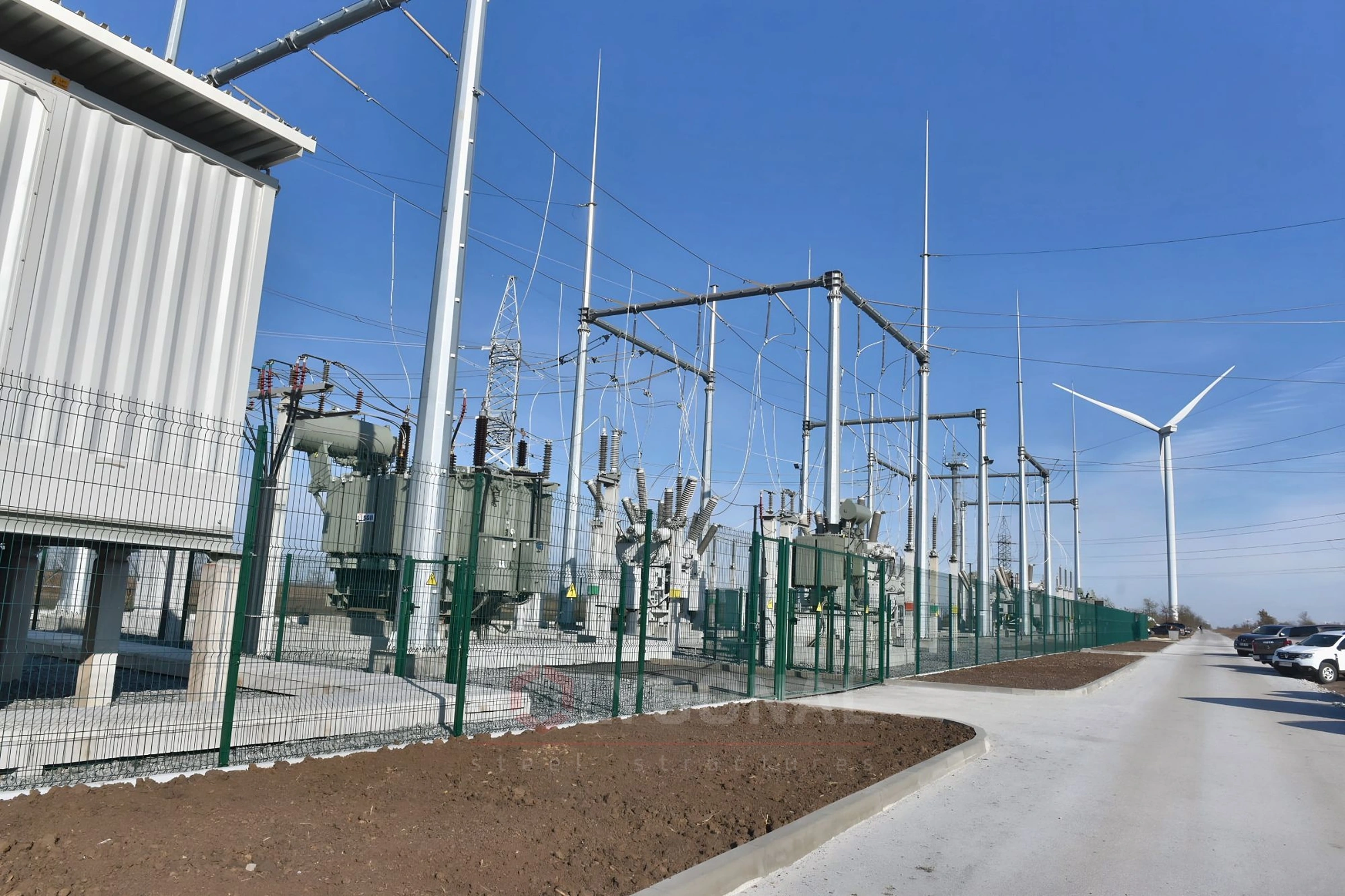
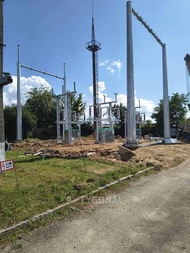
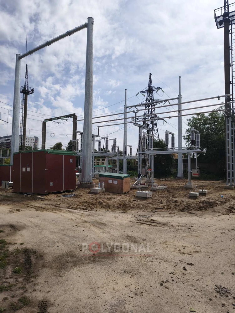
Zhuliany substation, Kyiv
150 kV gantries
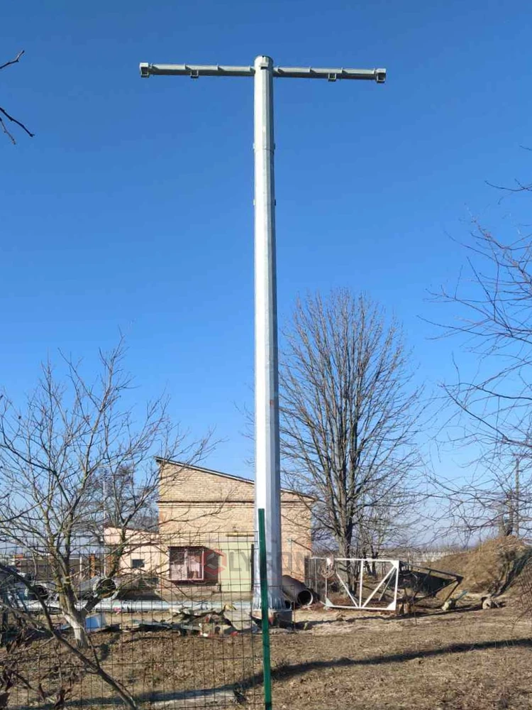
For 150 kV substations there is the catalogue 150 kV Steel Multi-Sided Switchyard Gantries (TP-PSM150.19.01): seven types Y1–Y7, all with a post height to the crossarm of 12,720 mm and a bay of 11,100 mm; with a ground-wire post and a lightning rod the post height reaches 25,220 mm. The types, erection schemes and the questionnaire are on the catalogue page.
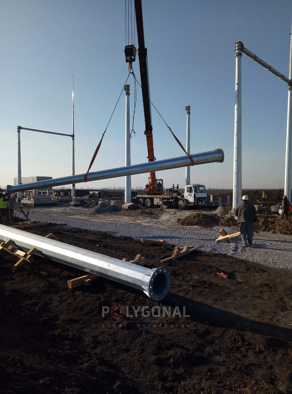
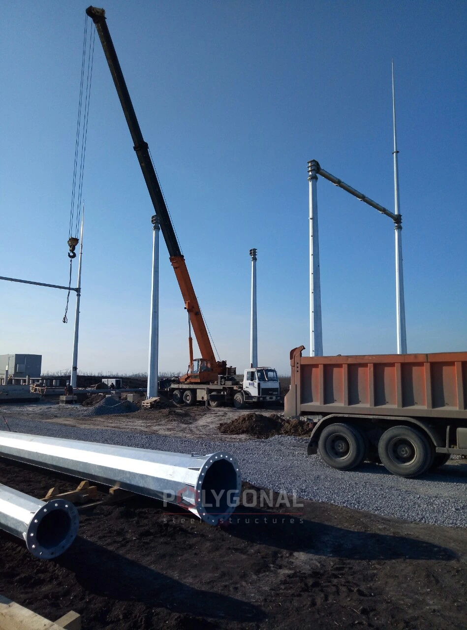
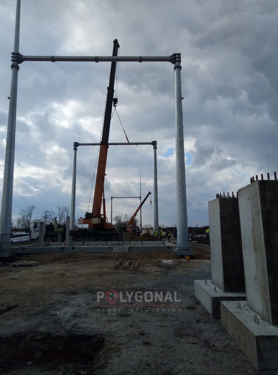
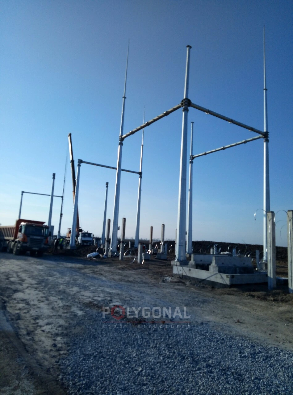
Installation of 150 kV gantries, Prymorska wind farm 2
Clearances on a gantry under the PUE: 35, 110 and 150 kV
Clearances on a gantry are set by Chapter 4.2 of the Rules for the Arrangement of Electrical Installations (PUE), 2026 edition; the Rules call an open switchyard ВРУ. The minimum clearances between bare live parts of different phases (АФ-Ф), from them to earthed structures (АФ-З), to the ground for unfenced live parts at the greatest conductor sag (Г) and to internal fences up to 1.6 m high (Б) must be taken from Table 4.2.1 (cl. 4.2.51, 4.2.54).
For 110 and 150 kV the table gives two figures: one for switchyards with valve-type arresters, the other for those with surge arresters (ОПН). The figures below are for surge arresters, because valve-type arresters are not used on newly built 35–750 kV substations or when they are reconstructed (cl. 4.2.172). For 35 kV there is a single value.
With flexible busbars the clearances are found from the formulas of cl. 4.2.52: the swing of the conductor in the wind, a = f·sin α, is added to the tabulated АФ-З and АФ-Ф. Here f is the conductor sag at +15 °C, α = arctg(P/G), and P and G are the wind load and the weight load per metre of conductor. The wind pressure in this calculation corresponds to 40 % of the service wind load on the conductor. With rigid busbars the table values are used.
Towards internal fences the horizontal clearance must be at least Б for a 1.6 m fence and at least АФ-З for a 2.0 m fence (in the plane of the fence), and the vertical clearance at least АФ-З from a point in the plane of the fence at a height of 2.7 m above the ground (cl. 4.2.54).
| Rated voltage | Between phases (АФ-Ф), mm | To earthed structures (АФ-З), mm | To ground (Г), mm | To an internal fence up to 1.6 m high (Б), mm |
|---|---|---|---|---|
| 35 kV | 440 | 400 | 3,100 | 1,150 |
| 110 kV | 750 | 600 | 3,300 | 1,350 |
| 150 kV | 1,050 | 800 | 3,500 | 1,550 |
PUE (2026 edition), Table 4.2.1; for 110 and 150 kV, the values for switchyards with surge arresters. At these voltages А¹Ф-З (conductor to post or crossarm) equals АФ-З. These are minimum clearances: the designer takes the final values for a specific substation from the current text of the PUE.
Lightning rods on a gantry
On the gantries of 15.75 and 35 kV switchyards with rod-type lightning rods, insulator strings rated for 110 kV must be used. On a switchyard with lightning rods, the air distance from a structure carrying a lightning rod to live parts must be no less than the length of the insulator string (PUE (2026 edition), cl. 4.2.163).
The PUE allows a lightning rod on a transformer gantry, a shunt reactor gantry or any other switchyard structure less than 15 m (along the earth electrode) from power transformers, shunt reactors or structures of 6–20 kV outdoor packaged switchgear (КРУЗ) only where the equivalent soil resistivity in the thunderstorm season does not exceed 350 ohm·m, and only subject to a number of further conditions. For a substation whose higher voltage is 35 kV, one of them is this: if the lightning rod stands on a transformer gantry, the earth-electrode resistance must be no more than 4 ohms, and earth electrodes outside the switchyard earth electrode are not counted (PUE (2026 edition), cl. 4.2.164).
How to order a gantry
To work out the price, send the voltage class, the mark or type of the gantry, the wind and ice regions, the seismicity and the site. Layouts and heights that are not in the tables are designed individually for the substation. Erection is carried out by a licensed construction partner company.
Updated:
Questions about multi-sided gantries for 35–150 kV
What sizes of polygonal portals for 35 and 110 kV do you make?
For 35 kV, the ПС-35…-Б series of six marks (ПС-35Ш-Б and ПС-35Я1-Б to ПС-35Я5-Б); for 110 kV, the ПС-110…-Б series of thirteen (ПС-110Ш-Б and ПС-110Я1-Б to ПС-110Я12-Б). Heights, bay lengths and the numbers of ground-wire posts and lightning rods are in the tables above. If you need a different layout, we design the portal individually.
How do the 110 kV marks Я1–Я12 differ?
In the number of bays (1 to 5), ground-wire posts and lightning rods. The height to the crossarm of 11.35 m and the 9 m bay are the same in all of them. The make-up of each mark is in the 110 kV table above.
Can I order a gantry of a non-standard height or layout?
Yes. Layouts and heights that are not in the tables are designed individually for the substation. Send the input data and we will work out an option.
Related products: Substation gantries · Hot-dip galvanising
More on this topic: Typical Substation Gantries 35–500 kV · Multi-sided Substation Gantries: Design and Foundations · Installing a Substation Gantry: Slinging, Setting the Shafts and Crossbeam, Tightening the Bolts · What Is a Substation Gantry: Purpose and Voltage Classes · Restoring Damaged Substation Switchyard Portals · Protective Structures for Substation Switchyard Equipment
Get a quote for your requirements
Send us your requirements — we will calculate the price and lead time.