
Steel multi-sided switchyard gantries 150 kV
Unified design solution TP-PSM150.19.01 (2019): gantries for 150 kV open switchyards. 13 pages. Document in Ukrainian.

Click the right or left half of the page to turn it; use the ← → keys, or swipe on a phone.
What’s in the catalogue
The «TP-PSM150.19.01» catalogue is a unified design solution for steel multi-sided gantries for 150 kV open switchyards, POLYGONAL, 2019.
Inside: general data and contents (p. 1), general notes — marking, design, materials, calculation (p. 2-3), installation schemes for 7 gantry types — PSM-150Y1 to PSM-150Y7 (p. 4-10), an order questionnaire (p. 11).
Key parameters
| Type | Bays | Length, m | Posts | Lightning rods |
|---|---|---|---|---|
| Y1 | 1 | 11.1 | 2 | 0 |
| Y2 | 1 | 11.1 | 2 | 1 |
| Y3 | 1 | 11.1 | 2 | 1 |
| Y4 | 2 | 22.2 | 3 | 2 |
| Y5 | 3 | 33.3 | 4 | 2 |
| Y6 | 3 | 33.3 | 4 | 0 |
| Y7 | 3 | 33.3 | 4 | 2 |
Post height to the crossarm is 12,720 mm for all 7 types; the bay (post spacing) is 11,100 mm. Posts with a ground-wire post and lightning rod reach up to 25,220 mm. From the TP-PSM150.19.01 catalogue.
Who it’s for
The gantries are designed for 150 kV open switchyards at substations — as line-entry, busbar and power-transformer gantries.
Suitable for wind regions 1-5, ice regions 1-6 (including combined wind-and-ice loads per PUE:2026), seismic intensity up to 6 points, pollution degree I-IV, air temperatures from −40 to +40 °C.
How to order
Manufactured to TU U 25.1-39573934-002:2018. Post cross-section is a regular dodecagon; all 7 types are calculated as terminal (anchor-type) gantries. Fixed to the foundation through a flange; the foundation is designed individually for the site’s geotechnical conditions. Hot-dip galvanising is at least 80 microns. Design service life is 50 years.
To order, state the gantry type (Y1-Y7) or the design loads and wind/ice region in the questionnaire (p. 11 of the catalogue) or in our technical specification form.
Example: reading the catalogue and choosing a gantry type
Say you need a gantry with three bays: 3 × 11.1 = 33.3 m, 4 posts. In the table above these are Y5, Y6 and Y7. They share the same frame and differ in ground-wire posts and lightning rods: Y6 (sheet 9) has no lightning protection, Y5 (sheet 8) has ground-wire posts on the end posts, and Y7 (sheet 10) has them on all four.
The height of an end post with a ground-wire post and a lightning rod is 12,720 + 5,000 + 7,500 = 25,220 mm. The crossarm of each bay is 2,550 + 3,000 + 3,000 + 2,550 = 11,100 mm, which equals the post spacing.
| Type | KS1 | SS1 | TR1 | TS1 | MP1 |
|---|---|---|---|---|---|
| Y1 | 2 | 0 | 1 | 0 | 0 |
| Y2 | 2 | 0 | 1 | 1 | 1 |
| Y3 | 2 | 0 | 1 | 2 | 1 |
| Y4 | 2 | 1 | 2 | 3 | 2 |
| Y5 | 2 | 2 | 3 | 2 | 2 |
| Y6 | 2 | 2 | 3 | 0 | 0 |
| Y7 | 2 | 2 | 3 | 4 | 2 |
KS1 – end post, SS1 – intermediate post, TR1 – crossarm, TS1 – ground-wire post, MP1 – lightning rod. Quantities are from the specifications on sheets 4–10.
What to take into account when designing and ordering
The gantries in the catalogue are free-standing flat portal frames: the posts are fixed in the foundations and rigidly joined to the crossarms (sheet 2). Phase conductors are attached within the crossarm bay, the ground wire at the top of the ground-wire post.
The questionnaire (sheet 11) has 44 items, all mandatory; where data is not available, a dash is entered. It is convenient to gather them in blocks:
| Items | What to state |
|---|---|
| 1–5 | Date, customer, standards for the calculation, gantry type, voltage |
| 6–18 | Site conditions: region and terrain type, atmospheric pollution, wind and ice regions, seismicity, temperatures, altitude above sea level |
| 19–30 | Conductors and ground wire: type, number, stress, insulator-string attachment, insulators |
| 31–35 | Span, gantry dimensions, clearance from conductors to the ground, conductor arrangement |
| 36–44 | Crossarms (multi-sided or lattice), post sections (number and height) and their joints, connection to the foundation, installation ladder, service life, corrosion protection, sketch, additional information |
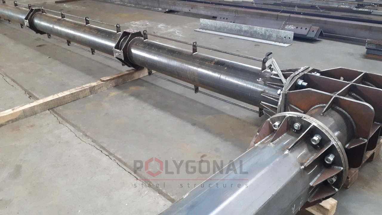
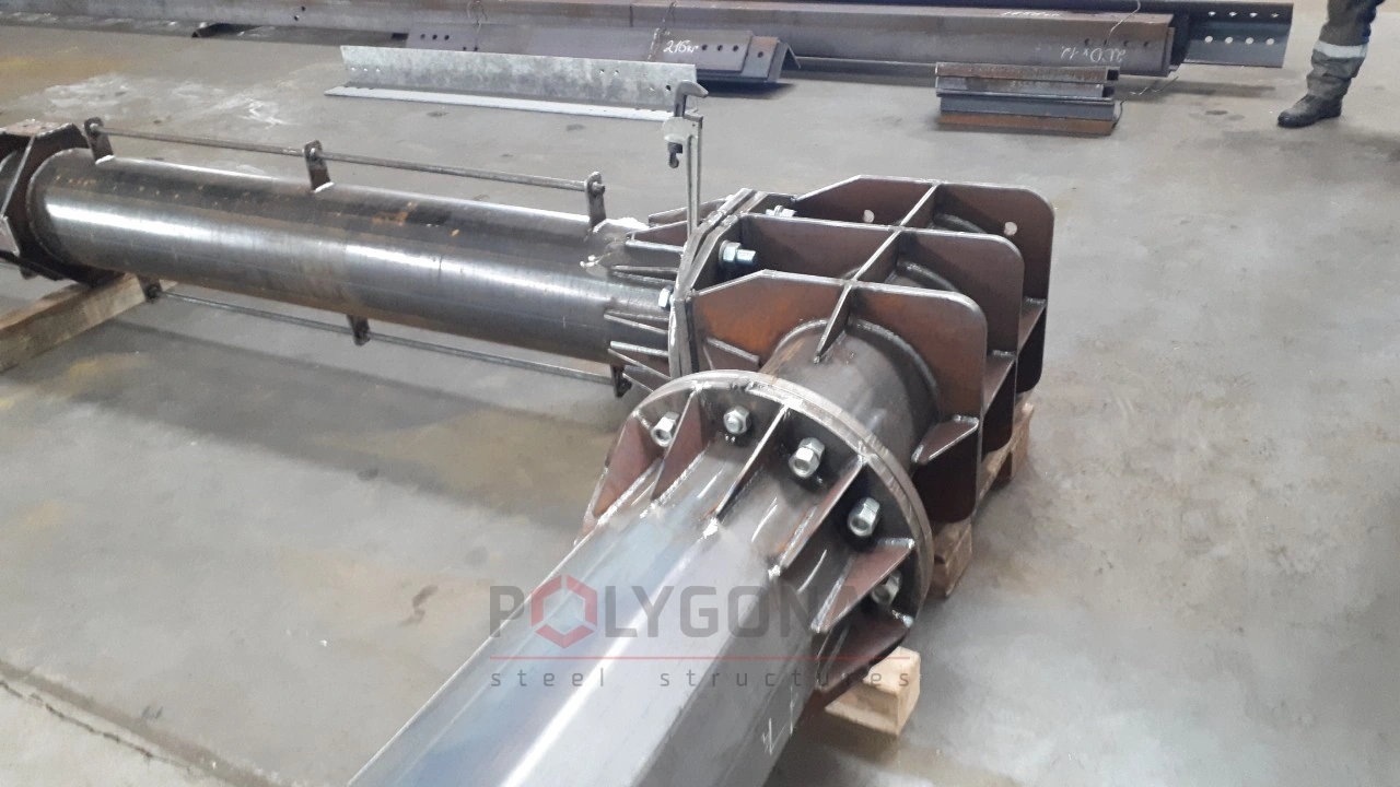
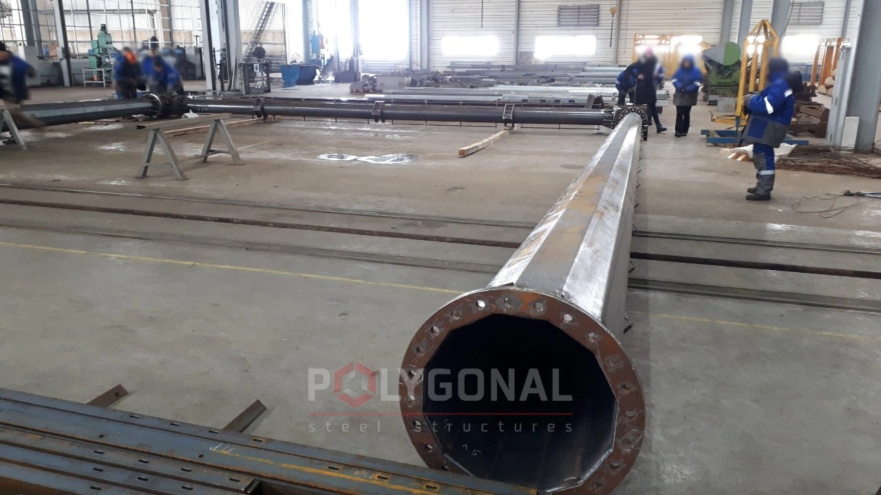
Control assembly of the gantry in the workshop
Before shipment, a 150 kV gantry goes through a control assembly in the workshop. It checks the dimensions of the structure, the erection joints of the shipping elements, and the match and position of the erection holes.
The photos show the control assembly of a 150 kV switchyard gantry in the workshop: the elements are joined with bolts.
Control assembly of the gantry
Related materials
Alongside the catalogue, these pages are useful:
- 110 kV gantries: a similar catalogue covering 12 types;
- Typical switchyard gantries 35–500 kV: marks, number of posts, mass;
- Gantry and foundation design: why multi-sided gantries beat the typical ones;
- Loads on overhead lines: wind, ice, temperature.
Questions about the 150 kV switchyard gantries
How do the 7 gantry types Y1-Y7 differ?
By the number of bays — from 1 to 3, i.e. a length from 11.1 to 33.3 m — and by the ground-wire posts and lightning rods fitted for direct-strike lightning protection: from none at all to protection on every post.
Can you make gantries for other voltage classes?
Yes, we manufacture similar gantries for 35, 110, 220, 330, 500 and 750 kV switchyards, calculated individually for the site’s input data.
How is a designation such as PSM-150Y7 read?
It is a steel multi-sided gantry for a 150 kV switchyard, of the bay (cell) type, type 7 (sheet 2). The type number matches the installation scheme: Y1 is on sheet 4, Y7 on sheet 10.
What does the catalogue require for installation, earthing and upkeep of the gantry?
Installation must be carried out by a specialised organisation following a work execution plan, and slinging and loading onto vehicles must not damage the zinc coating (sheet 3). Earthing follows PUE:2026, and after installation the earthing loops are measured (sheet 2). In service, the throughput of the condensate drain from the support unit is checked regularly, and tall vegetation around the gantry base, 1 m from its outline, is removed (sheet 3).
Get a quote for your requirements
Send us your requirements — we will calculate the price and lead time.