
Home / Products / Substation gantries / Multi-sided Substation Gantries: Design and Foundations
Substation gantries
Multi-sided Substation Gantries: Design and Foundations
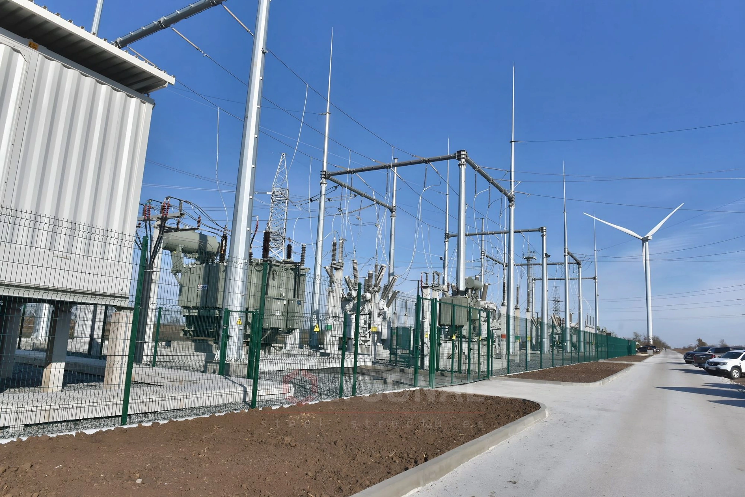
Modern switchyard portals based on steel polygonal bent poles replace outdated typical solutions. We compare them with typical lattice portals and explain how we design the portals and foundations.
Contents
- Polygonal switchyard portals: purpose and features
- How polygonal portals beat typical ones
- Design of foundations
- Earthing of a switchyard portal: what the PUE require
- What a multi-sided gantry consists of
- Stages of switchyard gantry design
- Catalogues and unified solutions
- What is needed for calculation and ordering
Polygonal switchyard portals: purpose and features
POLYGONAL designs and makes the steelwork of open switchyards: steel polygonal switchyard portals. They are used to hang busbars in open switchyards. The operating conditions and technological purpose of a portal are set when ordering and written into the technical specification.
We specialise in an individual approach: we design the steelwork of polygonal switchyard portals case by case, in accordance with the norms and rules in force in Ukraine.
The posts of steel polygonal portals have a flange joint with the foundation. The foundation is made as a tube with a flange.
How polygonal portals beat typical ones
The most obvious advantages of polygonal switchyard portals are that they can be installed in restricted conditions (small land allotment) and their durability. The considerable increase in service life comes from the closed polygonal profile, protected from corrosion by hot-dip galvanising inside and out.
Typical switchyard portals designed back in the 1970s and 1980s are still widespread. Typical lattice steel portals are heavy, need large outlay on assembly and erection, and take up a large area, so they cannot be used in restricted conditions. They were designed as welded structures with lap welds, which under galvanising rules cannot be galvanised, so hot-dip galvanising is ruled out as corrosion protection for typical portals. The design of typical portals does not reflect changes in design standards, new technologies and higher requirements for power-supply reliability. The damage from accidents at existing switchyards with imperfect portals is in some cases substantial.
These shortcomings can be overcome with a new generation of supporting structures based on steel polygonal posts. They are more reliable and durable than reinforced-concrete and lattice ones, more resistant to ice, wind and corrosion, quicker to erect and more resistant to vandalism.
Design of foundations
We design foundations for polygonal switchyard portals. The foundations are designed on the basis of, and taking into account:
- results of engineering-geological surveys for the construction;
- the seismicity of the construction area;
- data on the purpose, structural and technological features of the portals and foundations and the conditions of their operation;
- the loads acting on the polygonal portals and foundations;
- the size of the plot for the switchyard portal;
- a technical and economic comparison of possible design solutions, to choose the one that makes the most efficient use of the portals and foundations.
Earthing of a switchyard portal: what the PUE require
The earthing system of a switchyard is designed as part of the substation, but it concerns the portal and foundations directly: the structures are connected to it, and the foundations can serve as natural earth electrodes. Below are the requirements of the Rules for the Arrangement of Electrical Installations (PUE), 2026 edition, for outdoor installations above 1 kV.
A closed horizontal earth electrode must be laid around the area occupied by the equipment, at a depth of at least 0.5 m, and the exposed conductive parts that are to be earthed are connected to it (cl. 1.7.101; for networks with a solidly or effectively earthed neutral, cl. 1.7.107 requires the same closed loop). If the resistance of the earthing system is above 10 ohms (under cl. 1.7.113, for soil with a resistivity above 500 ohm·m), protective potential equalisation must be added: horizontal electrodes are laid in the ground along the rows of equipment on the service side, at a depth of 0.5 m and 0.8–1 m from the foundations or bases, after being connected to the earthing system (cl. 1.7.101).
The resistance depends on the neutral of the network. With a solidly or effectively earthed neutral, the earthing system is, as a rule, designed to the touch-voltage requirement (cl. 1.7.105, 1.7.114, Table 1.7.4); where natural earth electrodes of low resistance are available, it may be designed to the resistance requirement instead. In that case the resistance, counting artificial and natural earth electrodes together, must not exceed 0.5 ohm in any season, and longitudinal electrodes must be laid along the rows of equipment at a depth of 0.5–0.7 m and 0.8–1.0 m from the foundations (cl. 1.7.106).
If the neutral is isolated, compensated or earthed through a resistor and the earthing system serves only installations above 1 kV, or also installations up to 1 kV whose N, PEN (PE) conductors do not leave that system, then R ≤ 250/Ip, but not more than 10 ohms (Ip is the design earth-fault current, A; cl. 1.7.98). These rules do not cover the earthing of line poles: their resistance is determined under Chapter 2.5 (cl. 1.7.98, 1.7.103).
Rod-type lightning rods may be placed on the structures of switchyards of 15.75 kV and above where the equivalent soil resistivity in the thunderstorm season is up to 500 ohm·m (the area of the substation earth electrode does not matter then), or above 500 ohm·m if the substation earth electrode covers 10,000 m² or more. From a post of a 15.75–150 kV structure with such a lightning rod, the lightning current must spread through the earth electrode in at least two directions, with at least 90° between neighbouring ones (cl. 4.2.163).
In addition, vertical electrodes 3–5 m long are needed: at least two for 15.75 and 35 kV, or one for 110 and 150 kV. They are placed from the point where the earthing conductor of the post joins the earth electrode, no closer than the length of the electrode and no farther than 10 m. If the connection points of two neighbouring lightning rods are within 20 m of each other along the earth electrode, one electrode may serve both posts. On switchyards of 220 kV and above with lightning rods, the vertical electrodes may be omitted: the lightning current then spreads through the earth electrode (cl. 4.2.163).
On the portals of 15.75 and 35 kV switchyards with rod-type lightning rods, insulating suspensions rated for 110 kV must be used (cl. 4.2.163). For transformer portals, shunt-reactor portals and switchyard structures that stand closer than 15 m along the earth electrode to power transformers, shunt reactors or structures of 6–20 kV outdoor packaged switchgear (KRUZ), the PUE sets separate, stricter conditions (cl. 4.2.164). The lightning protection level and the requirements of DSTU EN 62305 are covered in the article lightning protection of masts and towers.
Metal and reinforced-concrete structures in contact with the ground can be used as natural earth electrodes, including reinforced-concrete foundations in non-aggressive, slightly aggressive and moderately aggressive environments (cl. 1.7.115). The suitability of foundations in terms of current density, the need to weld the reinforcing bars and to weld anchor bolts to them, and whether foundations can be used as earth electrodes in a strongly aggressive environment are determined by calculation (cl. 1.7.116). The designer takes the final values for a specific object from the current text of the PUE and the survey data.
What a multi-sided gantry consists of
A switchyard gantry consists of columns and a beam (cross-arm) from which the busbars are suspended. The columns are bent multi-sided steel shafts made from sheet steel with a longitudinal weld; the sections are joined by a telescopic joint or flanges. The columns are fixed to the foundation through a flange; the foundation is a pipe with a flange.
The number of columns, spans and heights depend on the voltage class and the switchyard scheme, so each gantry is calculated individually.
Stages of switchyard gantry design
- collecting the input data: substation layout drawings, voltage class, busbar loads, wind and ice region, soil conditions;
- calculating the loads and selecting the cross-sections of columns and beams;
- preparing KM and KMD drawings;
- designing the foundations;
- manufacturing, hot-dip galvanising to DSTU EN ISO 1461:2024 and shipment.
Catalogues and unified solutions
The designer section of the site holds the catalogues and unified design solutions we have prepared, which help to select a gantry and prepare the input data:
- Typical switchyard gantries 35–500 kV: marks, types, number of posts and mass;
- 110 kV gantries: unified design solution TP-PSM110.18.01;
- 150 kV gantries: unified design solution TP-PSM150.19.01.
Typical gantries are used after recalculation to the current standards, and we carry out this recalculation. See also the switchyard gantries page.
What is needed for calculation and ordering
Send the substation design data: voltage, layout drawings, busbar loads, construction region. We carry out the calculation, propose a multi-sided design or a modification of a standard gantry, and calculate the price and lead time.
Updated:
Polygonal switchyard portals: frequently asked questions
How is a polygonal switchyard portal better than a typical lattice one?
The closed polygonal profile is protected by hot-dip galvanising inside and out, while typical lattice portals are designed with lap welds that cannot be galvanised under the rules. A polygonal portal also has a smaller footprint — one post and one foundation instead of a wide base with guy wires.
How is the portal fixed to the foundation?
The posts of polygonal portals have a flange joint with the foundation, which is made as a tube with a flange.
What is taken into account when designing the portal foundation?
The results of geotechnical surveys, the seismicity of the area, the loads on the portal and foundation, the size of the plot, and a technical and economic comparison of design options.
Related products: Substation gantries · Hot-dip galvanising
More on this topic: Typical Substation Gantries 35–500 kV · Multi-Sided Switchyard Gantries 35–150 kV: Sizes, Heights, Bays · Installing a Substation Gantry: Slinging, Setting the Shafts and Crossbeam, Tightening the Bolts · What Is a Substation Gantry: Purpose and Voltage Classes · Restoring Damaged Substation Switchyard Portals · Protective Structures for Substation Switchyard Equipment
Get a quote for your requirements
Send us your requirements — we will calculate the price and lead time.