
Home / Products / Substation gantries / Installing a Substation Gantry: Slinging, Setting the Shafts and Crossbeam, Tightening the Bolts
Substation gantries
Installing a Substation Gantry: Slinging, Setting the Shafts and Crossbeam, Tightening the Bolts
The order for assembling and installing a multi-sided substation gantry: slinging the shaft, setting it on the foundation, lifting the crossbeam, and the final tightening and checking of the bolts. Based on the POLYGONAL instruction for the LP-110-2 gantry (110 kV).
Contents
What a gantry consists of and who installs it
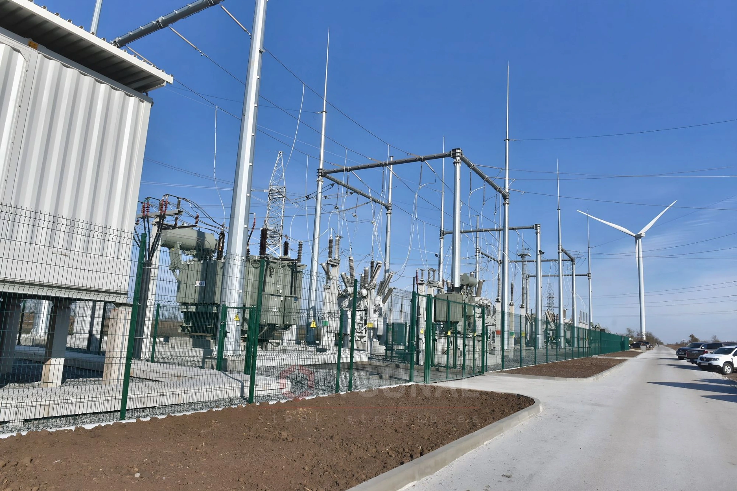
The LP-110-2 gantry (110 kV) is a single-span frame of two multi-sided shafts of 16-sided section, joined by a crossbeam through a flanged joint. The gantry is fixed to the foundation with a base flange and the foundation anchor bolts.
Installation is carried out by an installation contractor to a work execution plan (WEP). The diagrams in this article (figs 1–4; the labels on them are in Ukrainian) are recommendations: they are taken into account when the WEP is drawn up. POLYGONAL advises on assembly and installation, and the installation itself is done by a licensed construction partner company.
General notes on installing gantries are on the page Substation gantries.
Slinging the shaft
The shaft is slung with textile belt slings or steel ropes passed through rubber-fabric sleeves. The slings must be rated for at least 3 t.
The sling is applied as a choker hitch so that it sits at least 500 mm above the shaft’s centre of gravity. The crossbeam attachment point on the shaft stops the sling from sliding along it.
Bare steel ropes must not be used.
The diagram for lifting the shaft after slinging is fig. 1. It is a recommendation and is taken into account when the WEP is drawn up.
Setting the shafts on the foundation
After slinging, the shaft is erected on the foundation according to the technological maps of the WEP, which are prepared by a specialised design organisation.
The shaft is set according to the erection diagram, paying attention to where the crossbeam attachment point is. It is then temporarily fixed to the foundation (fig. 2) and aligned to the design position with the adjusting nuts.
After that the second shaft is slung and set on the foundation.
Installing the crossbeam
The crossbeam is assembled with the gantry shafts in this order:
- sling the crossbeam with soft slings so that no residual deformations or dents form that would damage the zinc coating;
- orient the crossbeam according to the erection diagram;
- lift it with the crane and guide it onto the shaft flanges (fig. 3);
- fit the bolts and tighten the nuts.
The diagram for slinging the crossbeam (fig. 3) is also a recommendation and is taken into account when the WEP is drawn up. Bare steel ropes must not be used.
Final tightening and checking of the bolted joints
Once the gantry has been aligned to the design position, all nuts of the bolted joints and of the foundation anchors are tightened for good, and only then are the slings removed. The joint between the shaft and the foundation is shown in fig. 4.
During installation it is strongly recommended to:
- align the gantry and fully tighten all nuts before the slings are removed, and remove the slings only after all foundation nuts are tightened;
- check the quality of tightening by tapping the bolts with a 0.4 kg hammer (a bolt must not tremble or move) and check that the joint is tight with a 0.3 mm feeler gauge, as clause 8.2.8 of DSTU B V.2.6-200:2014 requires;
- tighten the erection bolts to a torque of at least 15 kgf·m;
- on galvanised structures, tighten the nuts once more a week after the initial installation to make up for the compression of the zinc.
Diagrams from the instruction
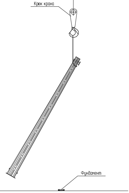
Fig. 1. Lifting the shaft after slinging
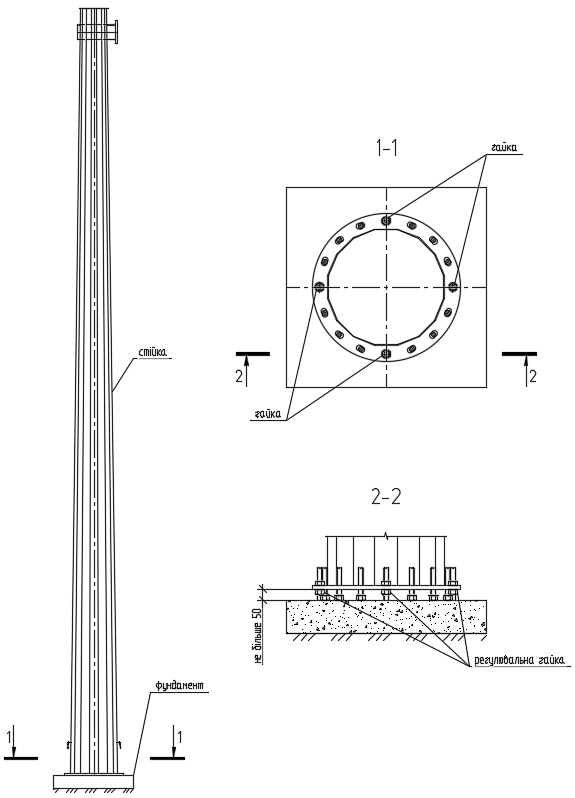
Fig. 2. Temporary fixing of the shaft to the foundation
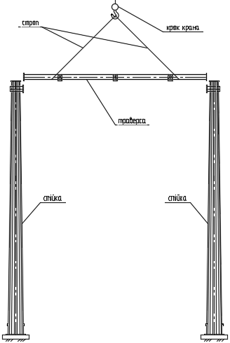
Fig. 3. Lifting the crossbeam after slinging
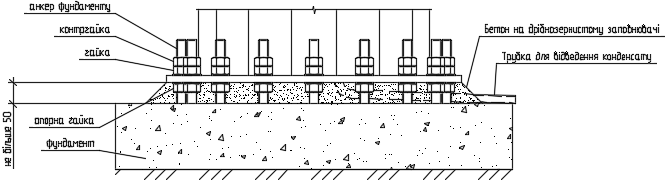
Fig. 4. Joint between the gantry shaft and the foundation
The customer’s technical supervision
The customer carries out technical supervision of the construction. During installation the customer checks:
- that the foundation has been built correctly;
- the accuracy of assembly;
- that the anchor bolt nuts are fixed securely;
- that the anticorrosion coating is undamaged.
How lighting poles, power line poles, masts and towers are assembled and installed is covered in Assembly, Erection and Installation of Multi-sided Poles, Masts and Towers, and the design of gantries and foundations in Polygonal Switchyard Portals: Advantages over Typical Designs, Design of Portals and Foundations.
Updated:
Gantry installation: frequently asked questions
What is used to sling a gantry shaft?
Textile belt slings or steel ropes in rubber-fabric sleeves, rated for at least 3 t. The sling is applied as a choker hitch at least 500 mm above the shaft’s centre of gravity. Bare steel ropes are not allowed.
When are the slings removed after the gantry is erected?
Only after all nuts of the bolted joints and of the foundation anchors have been tightened for good.
How is bolt tightening checked?
By tapping with a 0.4 kg hammer: a bolt must not tremble or move. Tightness of the joint is checked with a 0.3 mm feeler gauge (clause 8.2.8 of DSTU B V.2.6-200:2014). Erection bolts are recommended to be tightened to at least 15 kgf·m.
Why are the nuts tightened again after a week?
On galvanised structures this is recommended to make up for the compression of the zinc: the nuts are tightened once more a week after the initial installation.
Who installs the gantry?
An installation contractor to a work execution plan (WEP). POLYGONAL advises on assembly and installation; the installation itself is done by a licensed construction partner company.
Related products: Substation gantries
More on this topic: Typical Substation Gantries 35–500 kV · Multi-sided Substation Gantries: Design and Foundations · Multi-Sided Switchyard Gantries 35–150 kV: Sizes, Heights, Bays · What Is a Substation Gantry: Purpose and Voltage Classes · Restoring Damaged Substation Switchyard Portals · Protective Structures for Substation Switchyard Equipment
Get a quote for your requirements
Send us your requirements — we will calculate the price and lead time.