
Home / Services / Hot-dip galvanising / Designing Steel Structures for Hot-dip Galvanising: Holes, Welds, Stress
Hot-dip galvanising
Designing Steel Structures for Hot-dip Galvanising: Holes, Welds, Stress
Hot-dip galvanising needs a part with no air pockets, where molten zinc can flow in and drain freely. We collected practical rules from the ISO 14713-2:2019 guidance — for designers and customers.
Contents
Why a structure is designed for galvanising
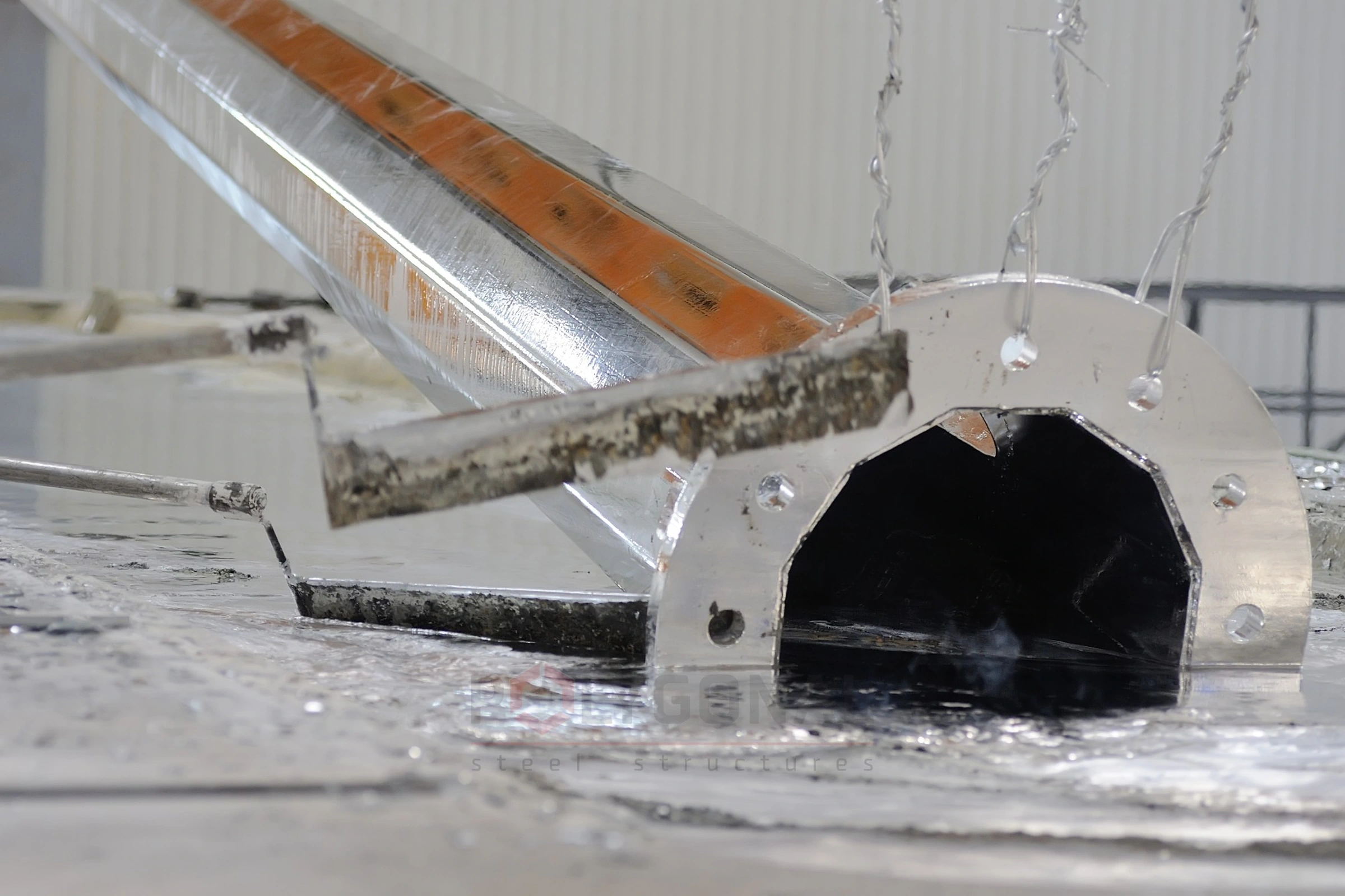
The part is dipped into a bath of molten zinc at about 450 °C, after first passing through degreasing, pickling and fluxing in separate baths. For every surface, outside and inside, to go through all of these steps, liquids, air and zinc must be able to enter every cavity and leave it freely.
An air pocket leaves the surface uncoated. It is even more dangerous when liquid stays trapped in a sealed volume: at melt temperature it boils, the pressure rises, and the part may warp or explode, endangering the people at the bath. That is why closed compartments are avoided or vented.
It is best to consult the galvanising plant before designing or fabricating: a small change of shape on the drawing costs far less than reworking a finished part. Compact assemblies that take little room in the bath are the cheapest to galvanise. Our bath is 13,000 × 1,600 × 3,200 mm (length × width × depth). If a part is larger than the bath, it can sometimes be dipped in two stages, turned over, but this is less common and is agreed separately. More about the service: Hot-dip galvanising.
Vent and drain holes
- place holes at both ends of a hollow member diagonally opposite, at the top and bottom, as close as possible to the sealed end or corner: air leaves at the top and zinc drains at the bottom;
- the larger the hole, the easier and cleaner the galvanising; a typical minimum for small parts is 10 mm in diameter, and for large ones the hole is about a quarter of the member’s diameter;
- cut-off corners work better than round holes because they have a larger cross-section; if the holes are round, put them as close to corners and edges as possible;
- in very long hollow sections (over 6 m) the holes must be larger or more numerous;
- in welded box sections the hole stays 10–20 mm away from the edge of the weld, depending on weld size: the thicker the weld, the farther the hole;
- in I-beams do not drill holes in the zone where the flange meets the web: it is better to vent through a stiffener or plate;
- holes and cut-outs are easier to make before assembly while corners are accessible; the exact position depends on how the part will be dipped, so agree it with the galvanising plant.
The recommended hole diameters and cut-out sizes for each section shape and size are given in Table A.2 of ISO 14713-2:2019. Use the current edition: older editions, and tables copied from them, give different figures.
Lap joints and narrow gaps
When two plates lie on top of each other, liquid from the pre-treatment baths can end up between them: in the melt it turns to steam. So overlapped areas are vented too, depending on the overlap area:
- up to 100 cm² — a weld all the way around the contour with no gaps; the parts must be dry, smooth and fit together without gaps;
- 100 to 1,000 cm² — two holes over 12 mm in diameter in diagonally opposite corners (or two weld interruptions over 25 mm long);
- 1,000 to 2,500 cm² — four such holes or interruptions in the corners;
- over 2,500 cm² — holes over 12 mm in the corners and then along the contour at no more than 300 mm intervals (or weld interruptions over 25 mm at the same spacing).
Narrow gaps between touching surfaces let liquid in, but zinc does not get in: later, stains run out of the gap and spoil the look of the coating. So welds are made continuous unless they close off an unvented space, and bolted joints are best assembled after galvanising.
Stress, thickness and shape of the part
After cold stamping, welding, flame cutting, drilling and even rolling, residual stress stays in the metal. At about 450 °C in the bath part of it is released, and the part may distort or, in rare cases, crack.
- design symmetric sections and avoid a sharp difference of thickness in one joint, for example a thin plate welded to thick angles: thin and thick metal heat and cool at different rates; for welded assemblies we ask for a ratio of the greatest to the smallest thickness of no more than 5:1;
- choose the welding order and method so that unbalanced stress and differential thermal expansion are as small as possible;
- if the stress is high, heat treatment may be needed before galvanising;
- avoid local cold deformation, and for bending keep to the minimum radii in the steel standards;
- quenched and high-strength steels with a yield strength above 650 MPa are more prone to cracking in the bath, so consult a specialist and relieve the stress before pickling;
- large flat sheets tend to warp: it is better to stiffen them with ribs or profiling, and to fix sheets on a frame with holes in the frame corners.
Steel and surface condition
The composition of the steel, above all silicon and phosphorus, decides the look and thickness of the coating: with silicon below 0.03% and phosphorus below 0.02% the coating is thin and bright, at 0.14–0.25% silicon it is bright or matt, and in the ranges 0.03–0.14% and above 0.25% it comes out thicker, darker and rougher. More on choosing the steel is in the preparation checklist.
Before pickling, everything that acid cannot remove is taken off the surface: paint, grease, rolling oil residue, markings, labels, glue, welding slag and anti-spatter sprays. Silicone-free sprays are preferable and should not be overused. Edges after flame, laser or plasma cutting are ground and sharp edges removed, otherwise the minimum coating thickness is harder to reach. For welds, wire or electrodes with a low silicon content are chosen so that the coating on the weld does not differ from the rest of the surface.
Tolerances, fixing and delivery for galvanising
- allow for the coating thickness on mating surfaces and in holes: on flat surfaces an allowance of at least 1 mm is considered acceptable;
- bolt threads are made to tolerance before galvanising and the nuts are tapped after it, or the bolts are made slightly smaller beforehand; an internal thread tapped after galvanising needs no coating;
- provide points for lifting and hanging (lifting lugs): in the bath the part is held at all times, and marks may remain where it touches a rack;
- stack galvanised parts securely; to keep «wet storage stain» to a minimum, tell the plant before galvanising, store parts with free air movement on spacers, and avoid shrink-wrap, which traps water;
- if the part will be painted or powder coated after galvanising (a duplex system), tell the plant in advance: the surface preparation requirements are agreed separately.
Updated:
Designing for galvanising: frequently asked questions
Why are holes needed in hollow parts?
Air leaves through them, and zinc enters and drains. Without holes, air or liquid stays in a sealed volume: no coating forms on the inner surface, and the part may warp or explode in the bath.
What is the minimum diameter of a vent hole?
For small parts the typical minimum is 10 mm, and for large ones the hole is about a quarter of the member’s diameter. Exact values for each section are in Table A.2 of ISO 14713-2:2019.
Can lap joints be galvanised?
Yes, but they must be vented: small areas up to 100 cm² are sealed with a continuous weld around the contour, while larger ones need holes in the corners depending on the area. Narrow gaps between touching surfaces are best avoided.
Why might a thin part welded to a thick one warp?
Thin and thick metal heat and cool in the bath at different rates, and welding stress adds to this. Symmetric sections, balanced welding and, if needed, heat treatment help.
Who should I agree the design with before fabrication?
With the galvanising plant, at the drawing stage: hole positions, hanging points and the orientation of the part in the bath depend on the dipping technique. Send us a drawing or photo and we will check the design for closed cavities and problem joints.
Related products: Hot-dip galvanising
More on this topic: Hot-dip Galvanising Process: Steps and Requirements · Hot-dip Galvanising Defects: Causes and Prevention · Zinc Coating Thickness under DSTU EN ISO 1461:2024 · Zinc Coating Defects: Runs, Grey Coating, Detachment and Black Spots · Hot-dip, Electro- or Cold Galvanising: Which to Choose · How to Prepare a Steel Structure for Hot-dip Galvanising: Checklist
Get a quote for your requirements
Send us your requirements — we will calculate the price and lead time.