
Home / Products / Street lighting columns / Road Lighting Poles: DMO
Street lighting columns
Road Lighting Poles: DMO
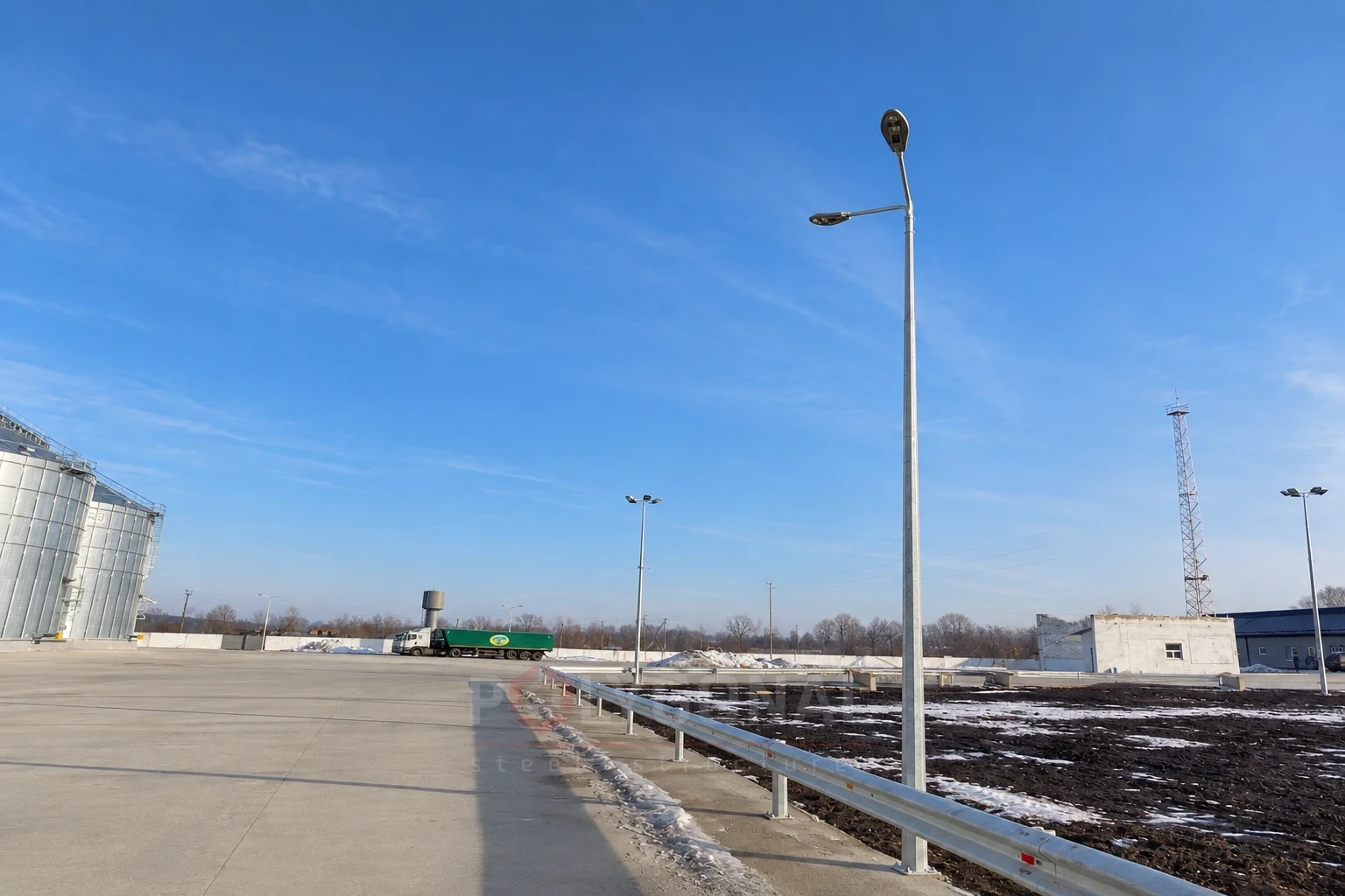
Multi-sided DMO road poles for lighting roads and highways. Also used as intermediate poles under SIP.
Contents
- Road lighting poles
- DMO poles under SIP (aerial bundled cable)
- Multi-sided road poles DMO
- How to check that a DMO pole suits your luminaire
- DMO or UMO at a height of 10 m: what changes
- A stretch of road with SIP: a worked example and what to confirm before ordering
- Selecting a pole by luminaire area and mass
Road lighting poles
Steel road lighting poles are used for streets, highways and roads of any traffic intensity, out-of-town stretches, the grounds of public buildings, residential blocks and courtyards. They fit both classic and modern urban landscapes and last a long time. If needed, the pole can be designed with fixings for extra equipment: solar panels, wind generators, batteries. Road lighting poles are multi-sided or round in section.
Multi-sided road poles are made of sheet steel 4 mm thick and are eight-sided in section. The material is chosen for the climate zone and the operating conditions. Coating: hot-dip galvanising to DSTU EN ISO 1461:2024, which greatly extends the service life.
Bracket-type and suspended luminaires are fitted to the poles. LED luminaires are now common: they save electricity and last longer. If you need a lighting design, a design of the poles themselves at stages KM and KMD, and manufacture, we will do it all as one package. Installation is carried out by a licensed construction partner company.
Prices of DMO poles
Indicative prices per piece including VAT (September 2026), excluding brackets, anchor cage, delivery and installation. All ranges and what the price includes: Lighting pole prices.
| Range | Purpose | Heights | Price, UAH incl. VAT per unit |
|---|---|---|---|
| DMO | Multi-sided road poles (for SIP cable) | 7–12 m | 25,000 – 39,000 |
DMO poles under SIP (aerial bundled cable)
We use DMO multi-sided road poles, 7 to 12 m high, for more than lighting: they are suitable for use with SIP (self-supporting insulated conductor, known as aerial bundled cable). The poles are designed as intermediate poles with a double bracket. One pole can carry both a luminaire and the line.
- double bracket: height up to 2 m, reach up to 2 m;
- the cable is hung at a height of up to 7 m;
- cable size up to 4×35;
- distance between poles up to 40 m.
Power reaches these poles by an overhead line. DMO poles come with a 500 × 120 mm inspection hatch.
Multi-sided road poles DMO
Designation example for a multi-sided road lighting pole 10 m high: DMO-10 TU U 25.1-39573934-001:2016.
Pole dimensions (DMO)
The dimensions W, v and Wp describe the inspection hatch: all DMO poles come with a 500 × 120 mm hatch.
| Pole mark | H, m | ∅a, mm | ∅b, mm | W, mm | v, mm | Wp, mm | B, mm | n×d, mm |
|---|---|---|---|---|---|---|---|---|
| DMO-7 | 7 | 110 | 238 | 500 | 120 | 500 | 220 | М24/4 |
| DMO-8 | 8 | 110 | 238 | 500 | 120 | 500 | 220 | М24/4 |
| DMO-9 | 9 | 110 | 238 | 500 | 120 | 500 | 300 | М27/4 |
| DMO-10 | 10 | 110 | 238 | 500 | 120 | 500 | 300 | М27/4 |
| DMO-11 | 11 | 110 | 238 | 500 | 120 | 500 | 300 | М27/4 |
| DMO-12 | 12 | 110 | 238 | 500 | 120 | 500 | 300 | М27/4 |
Scope of application (DMO)
The table gives the total area of lighting fittings (Caer = 1, terrain type III) by wind pressure. Q and M are the loads at the pole base.
| H, m | Hs, m | S, m | Equipment mass, kg | Q, kN | M, kN·m | 400 Pa, m² | 450 Pa, m² | 500 Pa, m² | 550 Pa, m² | 600 Pa, m² |
|---|---|---|---|---|---|---|---|---|---|---|
| 7 | – | – | 50 (on the axis) | 3,05 | 16,55 | 2,38 | 1,92 | 1,56 | 1,26 | 1,02 |
| 8 | – | – | 50 (on the axis) | 3,06 | 16,94 | 1,78 | 1,40 | 1,10 | 0,86 | 0,66 |
| 9 | – | – | 50 (on the axis) | 3,11 | 17,35 | 1,30 | 0,97 | 0,72 | 0,52 | 0,36 |
| 10 | – | – | 50 (on the axis) | 3,19 | 17,67 | 0,90 | 0,63 | 0,43 | 0,25 | 0,11 |
| 11 | – | – | 50 (on the axis) | 3,12 | 17,78 | 0,57 | 0,35 | 0,16 | 0,02 | – |
| 12 | – | – | 50 (on the axis) | 2,85 | 17,68 | 0,30 | 0,10 | – | – | – |
| 7 | 9 | 2,0 | 15 (on a 1-arm bracket) | 3,05 | 16,55 | 1,92 | 1,529 | 1,21 | 0,96 | 0,74 |
| 8 | 10 | 2,0 | 15 (on a 1-arm bracket) | 3,06 | 16,94 | 1,44 | 1,10 | 0,84 | 0,63 | 0,45 |
| 9 | 11 | 2,0 | 15 (on a 1-arm bracket) | 3,11 | 17,35 | 1,03 | 0,75 | 0,53 | 0,34 | 0,20 |
| 10 | 12 | 2,0 | 15 (on a 1-arm bracket) | 3,19 | 17,67 | 0,71 | 0,46 | 0,27 | 0,11 | – |
| 11 | 13 | 2,0 | 15 (on a 1-arm bracket) | 3,12 | 17,78 | 0,43 | 0,21 | 0,05 | – | – |
| 12 | 14 | 2,0 | 15 (on a 1-arm bracket) | 2,85 | 17,68 | 0,18 | – | – | – | – |
| 7 | 9 | 2х2,0 | 2х15 (on a 2-arm bracket) | 3,05 | 16,55 | 0,87 | 0,68 | 0,52 | 0,40 | 0,30 |
| 8 | 10 | 2х2,0 | 2х15 (on a 2-arm bracket) | 3,06 | 16,94 | 0,63 | 0,47 | 0,34 | 0,24 | 0,15 |
| 9 | 11 | 2х2,0 | 2х15 (on a 2-arm bracket) | 3,11 | 17,35 | 0,43 | 0,30 | 0,19 | 0,10 | 0,03 |
| 10 | 12 | 2х2,0 | 2х15 (on a 2-arm bracket) | 3,19 | 17,67 | 0,28 | 0,16 | 0,06 | – | – |
| 11 | 13 | 2х2,0 | 2х15 (on a 2-arm bracket) | 3,12 | 17,78 | 0,14 | 0,03 | – | – | – |
| 12 | 14 | 2х2,0 | 2х15 (on a 2-arm bracket) | 2,85 | 17,68 | 0,01 | – | – | – | – |
Symbols
H — pole height; Hs — height of the pole with bracket; S — bracket reach from the pole axis;
∅a — top diameter; ∅b — bottom diameter; W — height of the access hatch; v — hatch width; Wp — distance from the hatch to the base of the pole;
B — centre distance between the base flange holes; n×d — number and diameter of anchor bolts;
Q — shear force at the pole base; M — bending moment at the pole base.
How to check that a DMO pole suits your luminaire
The “Scope of application (DMO)” table above gives, for each height, the permitted total windage area of the luminaires at a wind pressure of 400–600 Pa and a mass limit: up to 50 kg on the axis or up to 15 kg per bracket arm. For a first estimate, compare the pressure with W0 (1 kPa = 1,000 Pa) and take the next higher column; for anything below 400 Pa, take the 400 Pa column. For example, the reference W0 for Kyiv is 0.37 kPa (370 Pa), so the 400 Pa column; for Lviv it is 0.52 kPa (520 Pa), so 550 Pa. This is a rough guide, not a selection for a project: W0 is only a baseline characteristic of the site, and the design load also depends on the height, terrain type, topography and shape of the pole. The final column is confirmed by calculation; see Wind Regions of Ukraine.
Take, for example, a luminaire weighing 12 kg (within the 15 kg limit) with a windage area of 0.25 m². The values are illustrative: for a real luminaire, use the figures from its datasheet. The table below shows the highest pressure at which one such luminaire is suitable on a 1-arm bracket, and the same for two of them (0.5 m² together) on a 2-arm bracket with a 2 m reach per arm. If you use the 400 Pa column (as for Kyiv), one luminaire is suitable on poles from DMO-7 to DMO-11; with the 550 Pa column (Lviv), only on DMO-7, DMO-8 and DMO-9. The example shows how to read the table; it does not replace selection for a particular site.
| Pole | One luminaire, 0.25 m² (1-arm bracket) | Two luminaires, 0.5 m² together (2-arm bracket) |
|---|---|---|
| DMO-7 | up to 600 Pa | up to 500 Pa |
| DMO-8 | up to 600 Pa | up to 400 Pa |
| DMO-9 | up to 550 Pa | not suitable |
| DMO-10 | up to 500 Pa | not suitable |
| DMO-11 | up to 400 Pa | not suitable |
| DMO-12 | not suitable | not suitable |
Based on the “Scope of application (DMO)” table (Caer = 1, terrain type III). “Not suitable” means that even at 400 Pa the permitted area is smaller than required. The permitted area drops quickly as the height increases: on a 1-arm bracket at 500 Pa, from 1.21 m² on the DMO-7 to 0.05 m² on the DMO-11, and for the DMO-12 the table does not allow this pressure at all. So choose the lowest height that satisfies the lighting calculation.
DMO or UMO at a height of 10 m: what changes
Both ranges are multi-sided with a 4 mm wall thickness, but the DMO has different dimensions, mass and flange, so one cannot be substituted for the other just because the height matches. The DMO-10 is 60.5 kg heavier (194.5 − 134), i.e. about 45%, and the permitted luminaire area on a 1-arm bracket at 500 Pa is almost three times smaller: 0.27 versus 0.807 m². The figures are taken from the tables on this page and on the UMO and UKO page.
| Parameter | DMO-10 | UMO-10 |
|---|---|---|
| Mass, kg | 194.5 | 134 |
| Top / bottom diameter, mm | 110 / 238 | 60 / 206 |
| Access hatch, mm / from base, mm | 500 × 120 / 500 | 500 × 90 / 600 |
| Flange B, mm / anchors | 300 / 4 × M27 | 220 / 4 × M24 |
| Bracket reach / height with bracket, m | 2 / 12 | 1.5 / 11 |
| Permitted area on the axis at 500 Pa, m² | 0.43 | 1.012 |
| Permitted area on a 1-arm bracket at 500 Pa, m² | 0.27 | 0.807 |
The hatch is given as height × width; the second figure is the distance from the hatch to the base of the pole. An anchor cage for the UMO-10 (B = 220 mm, M24) will not fit the DMO-10: the flanges are different.
A stretch of road with SIP: a worked example and what to confirm before ordering
An illustrative example: a straight stretch of road 800 m long with a SIP line, poles in a single row and spacing of up to 40 m. At least 800 ÷ 40 = 20 spans are needed, i.e. 21 poles: 19 intermediate DMO poles and two end poles, which are calculated separately. By the mass table, the 19 intermediate DMO-10 poles weigh 19 × 194.5 = 3,695.5 kg. Anchor cages and luminaires are not included, and the delivery set (brackets included) is confirmed when the order is placed, so for delivery planning this is only a rough guide. The masses of other DMO heights, from 131.0 kg for 7 m to 228.8 kg for 12 m, are given in Lighting Pole Height and Mass: Table by Range.
For 11–12 m poles, the rule of 3–4 mounting heights (Distance Between Street Lighting Poles) gives 33–48 m, but with SIP the spacing does not exceed 40 m. The DMO is designed as an intermediate pole: it only supports the line. Terminal and tension poles take the tension of the wires, and angle poles also take the resultant force at a change of direction of the route, so the end poles, the corners of the route and the branch points are calculated separately (see Power Line Pole Types by Purpose).
Before ordering, confirm the following (the data can be sent in any form; see How to Order Poles and Masts):
- the datasheet mass and windage area of the luminaires and the number of bracket arms;
- the construction region, which sets the wind pressure;
- for a SIP line: the cable size (up to 4×35) and the hanging height (up to 7 m);
- the overall height: a pole with its bracket is 2 m taller than the pole alone (14 m for the DMO-12); check this against the wires of other lines and tree canopies.
Selecting a pole by luminaire area and mass
You do not have to look up the permissible luminaire area in the “Scope of application” table by hand: the pole selection calculator by luminaire area and mass compares your luminaires with these data and shows which poles suit the height, wind region and mounting scheme.
Updated:
Frequently asked questions about DMO poles
How many luminaires can a DMO pole carry?
As many as the “Scope of application (DMO)” table permits: up to 50 kg on the axis or up to 15 kg per arm. The total windage area must also stay within the figure for the wind pressure at the site. Take the mass and area from the luminaire datasheet. For example, on a DMO-9 at 500 Pa, luminaires with a total windage area of up to 0.19 m² can be fitted on a 2-arm bracket and up to 0.53 m² on a 1-arm bracket.
Which anchor cage fits a DMO pole?
One whose flange dimension B and anchors match the dimension table: for DMO-7 and DMO-8 it is the FPO-1500-2 (B = 220 mm, M24 anchors), for DMO-9 to DMO-12 the FPO-1500-3 (B = 300 mm, M27 anchors). We confirm the final designation against the drawing when the order is placed; see Foundation Anchor Cages FPO, FPM, FKM. An anchor cage for the UMO will not fit.
Related products: Street lighting columns
More on this topic: Street Lighting Norms: Categories A, B, C under DBN V.2.5-28:2018 · Flanged or Direct-buried Lighting Poles: Which to Choose · Steel or Concrete Lighting Poles: Comparison · Lighting Pole Marking: PMO, UMO, DMO, OGK, NFG — Finding an Equivalent · Lighting Column Dimensions and Tolerances under EN 40-2: Heights, Brackets, Hatches, Flanges · Lighting Pole Height and Mass 3–12 m: Table by Range
Get a quote for your requirements
Send us your requirements — we will calculate the price and lead time.