
Home / For Designers / Manufacture of Lighting Poles: Technology
Knowledge base
Manufacture of Lighting Poles: Technology
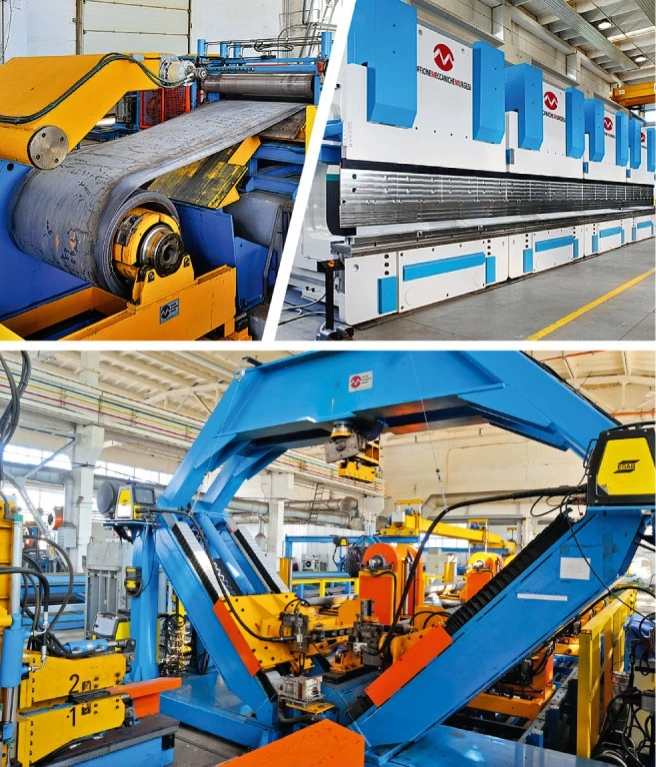
The technology for making steel lighting poles from coil and plate, bending sheet up to 12 m long on a press with a force of 2000 t.
Contents
The technology and its advantages
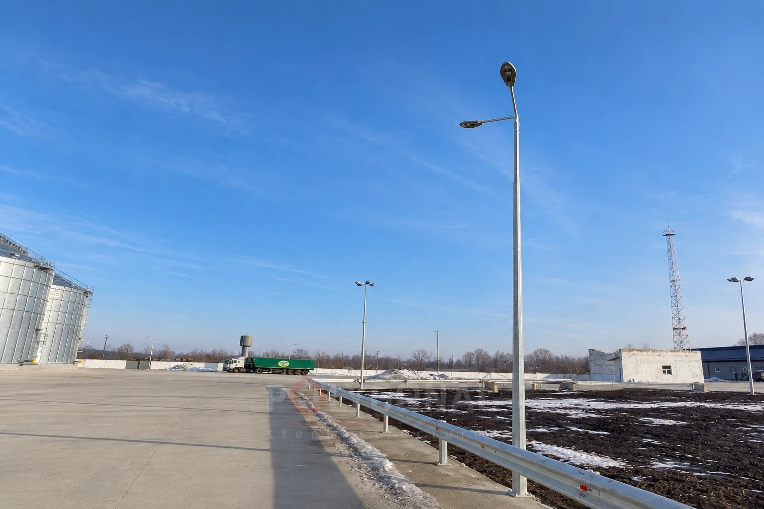
Steel street lighting poles are made from coil and plate. Sheet up to 12 m long is bent on a universal plate-bending press with a force of 2000 t. The process produces multi-sided pyramidal and smooth tapered poles for lighting streets and roads, poles for urban transport overhead lines, and floodlight masts.
Multi-sided steel poles for outdoor lighting and floodlight masts have better mechanical properties than reinforced concrete poles, and they are more reliable and last longer. A steel multi-sided shaft also has a higher load capacity than a concrete one, so it can be used in harsher conditions.
Besides multi-sided poles in many diameters and wall thicknesses, the line can also make smooth cylindrical pipes, large profile pipes and bent profiles for construction and engineering. That keeps the equipment better loaded.
The technology
Product range
The line produces:
- multi-sided pyramidal poles with a nominal diameter of 50–650 mm and a wall thickness of 3.0–8.0 mm for outdoor lighting lines, urban transport overhead lines and lighting masts;
- smooth tapered lighting poles 60–180 mm in diameter with a wall thickness of 3.0–4.0 mm for outdoor lighting lines;
- five-sided U-shaped sections 240×310×8.0 mm for poles of overhead contact lines on railway main lines.
To use metal efficiently and keep the equipment busy, the line can also make square and rectangular welded hollow sections (80×80 to 500×500 mm and 100×80 to 500×450 mm, wall thickness 3.0–14.0 mm, to EN 10219-1,2), angles and L-shaped bent profiles (40×40 to 140×140 mm, thickness 6.0–12.0 mm, EN 10162) and U-shaped bent profiles (100×60 to 500×380 mm, thickness 6.0–20.0 mm, EN 10162). This metal product can also be used in the plant’s own pole structures and in making fittings.
Requirements for blanks
The starting blank for making masts is hot-rolled steel in coils and plates, with dimensions matching those of the products:
- coils: outside diameter 1000–2000 mm, inside diameter 650–850 mm, strip thickness 3.0–8.0 mm, strip width 470–1500 mm, maximum coil weight 15 t;
- plates: thickness 6.0–8.0 mm, length 6000–12000 mm.
The blank is made of carbon and low-alloy structural steel. Mechanical properties of the steel: tensile strength no more than 650 N/mm², yield strength no more than 520 N/mm², elongation at least 20%. The sweep (camber) of plates must not exceed 3 mm per 1 m of length; the surface quality must meet the requirements for hot-rolled plate (excluding defects that take the wall thickness outside the limit deviations). Plates must not be repaired by welding.
When ordering metal, state that the steel products must be suitable for hot-dip galvanising. The recommended silicon content of the steel is 0.15–0.25%, and sulphur and phosphorus together must not exceed 0.04%.
Standards
The following standards apply to the poles and the lines they are used on:
- DBN V.2.6-198:2014 “Steel structures. Design standards”;
- the Rules for the Arrangement of Electrical Installations (PUE), 2026 edition;
- TU U 25.1-39573934-001:2016 “Steel structures of radio-relay communication poles, outdoor lighting and urban transport contact lines”.
Poles and masts are made by cold bending of sheet metal and arc welding under flux or in shielding gas without heat treatment of the weld. The surface of the poles must be smooth, as befits the production method; minor thickening, dents and longitudinal marks that come from the process are acceptable as long as the thickness stays within the permitted deviations everywhere. The manufacturer may remove surface defects by grinding, but after repair the wall thickness must not be less than the minimum permitted.
Welding and weld inspection
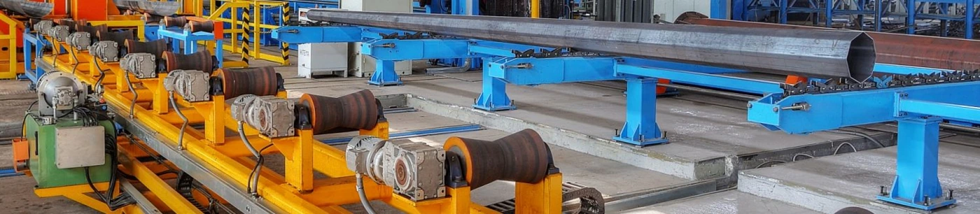
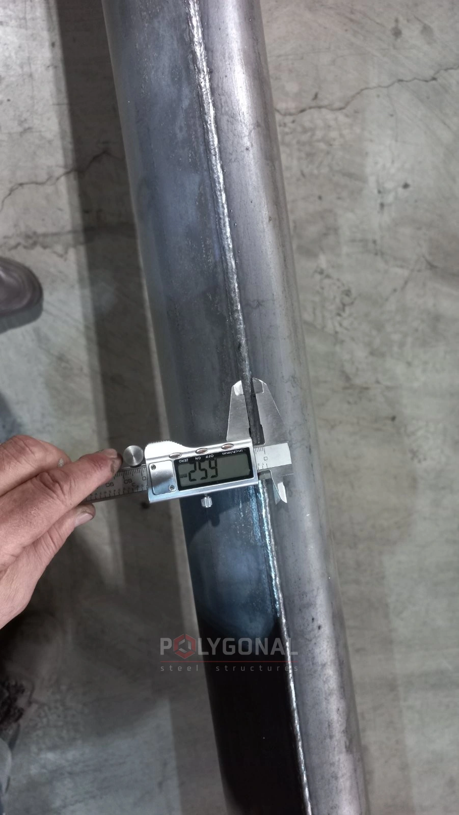
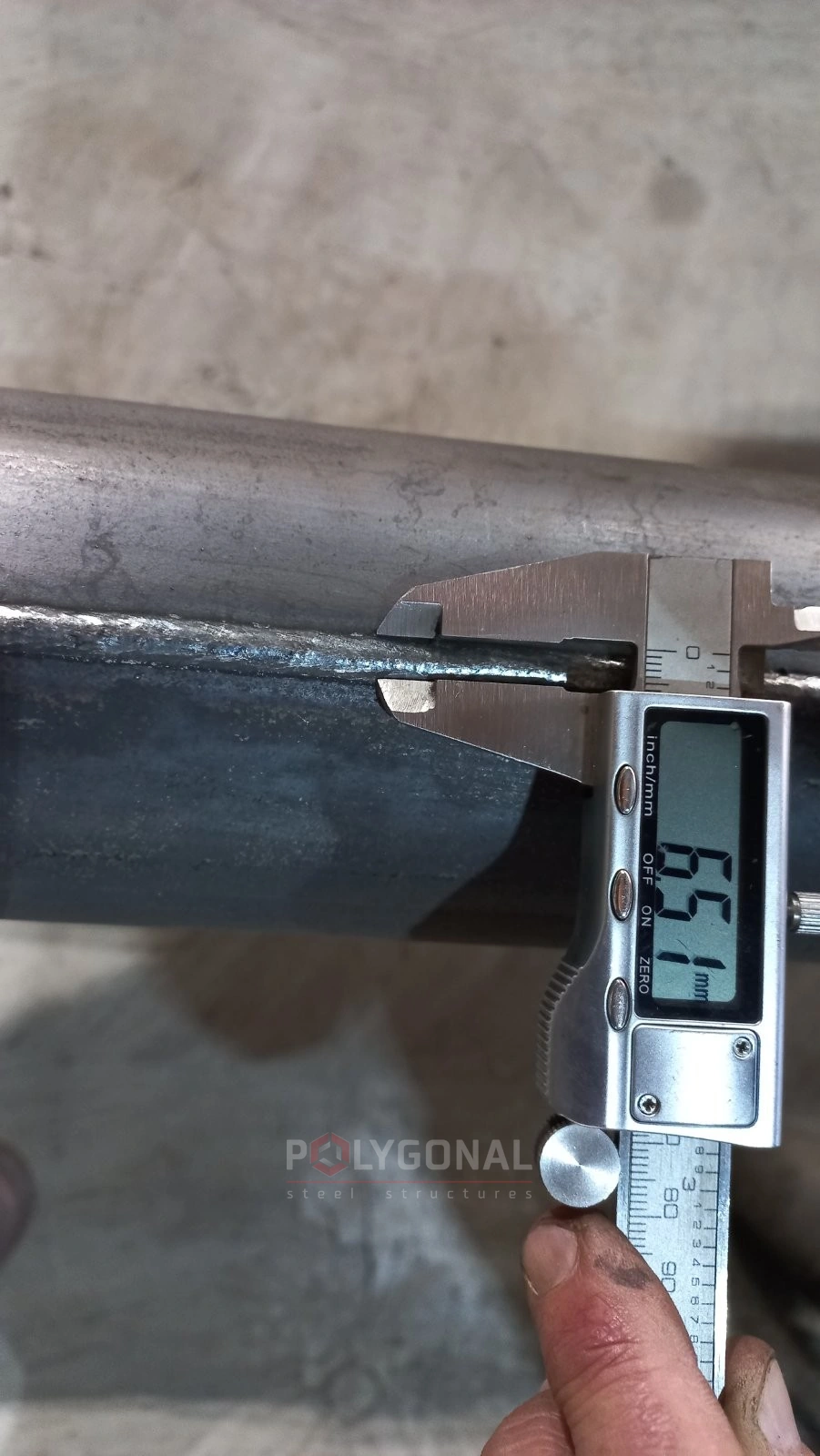
The welds of single-seam poles up to 650 mm in diameter are made by arc welding under flux or in shielding gas; welds of two-seam poles are made as a continuous weld in shielding gas. The reinforcement height of external welds is 0.5–3.0 mm, and of the weld bead on the inner surface up to 0.5 mm.
Welded joints are checked visually and by ultrasonic testing. Defective areas of welds can be repaired by cleaning and re-welding: the total length of repaired longitudinal weld areas is no more than 10% of the length of the pole’s welded joint, and a single repaired area must be at least 50 mm long. Craters inside the pole formed when welding is stopped and restarted may be welded up. Shrinkage marks along the weld axis are acceptable too, provided the reinforcement height stays within the minimum.
The welding consumables are flux, welding wire of the appropriate type, welding-grade carbon dioxide and argon gas.
Welding and weld inspection
Main process operations
- delivery of plate and coils to the warehouse, unloading and storage;
- uncoiling, straightening the strip and cutting it into trapezoidal blanks of set length;
- marking the cut sheets and plate (steel grade, thickness, width, length);
- cleaning the plate of dirt and foreign objects;
- gas-plasma cutting of the plate into trapezoidal blanks; checking the geometry of the blanks;
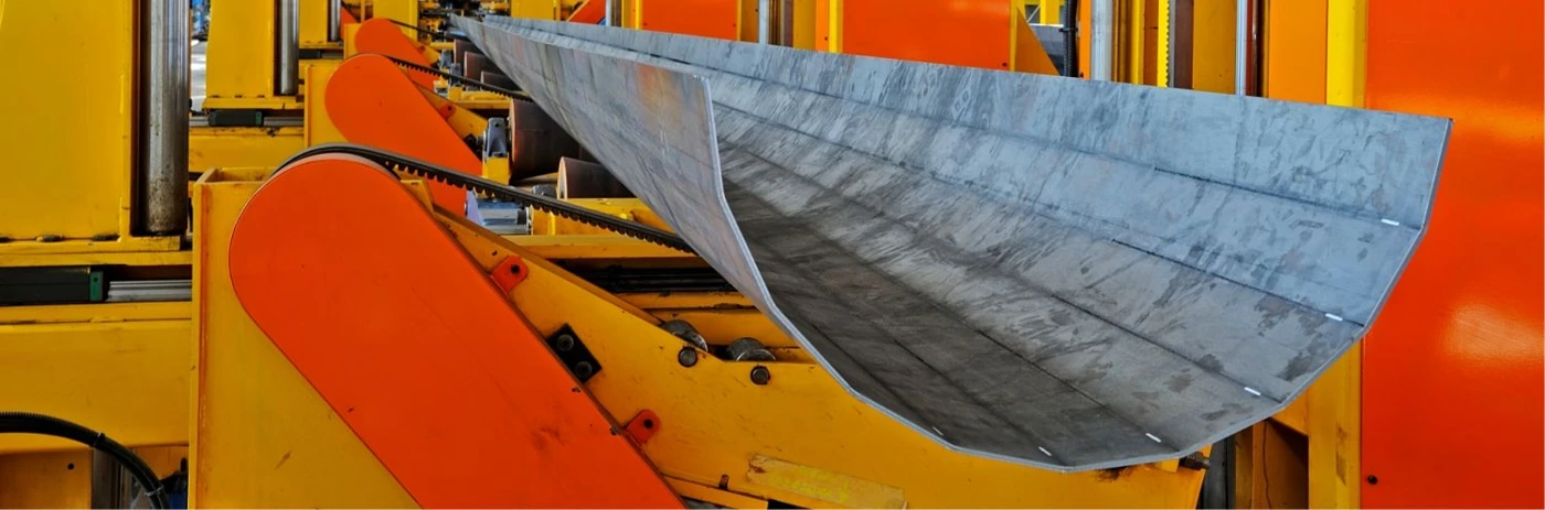
- step forming: multi-pass bending of areas from the edge of the blank to the middle of the profile simultaneously along its whole length;
- welding of longitudinal seams; visual and ultrasonic inspection;
- visual inspection and repair of poles;
- plasma trimming of strips and defective pipe ends; cutting samples for mechanical tests; plasma cutting of hatches;
- dressing the reinforcement of the external weld in the slip-joint zone;
- straightening the longitudinal curvature of the poles, calibrating the pole ends;
- welding on the base flange;
- acceptance of the poles.
How the blank is formed
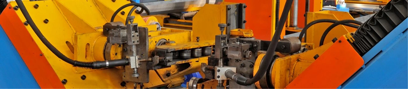
Step forming is done on the press by multi-pass bending of areas of the blank profile. For multi-sided lighting poles this is free bending: multi-pass stamping of profile areas on tooling made up of a narrow punch and a sector die. For cylindrical and tapered poles it is bottoming bending: multi-pass bending with a punch of a given radius and a matching die.
The control system records the final forming force and the working stroke of the bending beam, taking the wall thickness and steel strength class into account. After each cycle the residual deformation (springback) is evaluated and compared with the calculated values; the data go into a database and are used to correct the tool stroke.
Updated:
Manufacturing lighting poles: frequently asked questions
What press bends the sheet for poles?
A universal press brake with 2000 t of force, capable of bending sheet up to 12 m long.
What silicon content is recommended in steel for hot-dip galvanised poles?
0.15–0.25%, with total sulphur and phosphorus content no more than 0.04%. This is specified separately when ordering the metal.
How does forming multi-sided poles differ from cylindrical and tapered ones?
Multi-sided poles are formed by free multi-pass bending on a narrow punch and sector die; cylindrical and tapered ones by bottoming bending with a punch of a given radius and a matching die.
Questionnaire: technical assignment form
Fill in the form and email it to us: we will prepare the KM-stage design documentation from it and calculate the price. The PDF is handy to print; the DOCX can be filled in on a computer.
Technical assignment form: floodlight mast (lighting pole)
A questionnaire for preparing KM-stage design documentation for a steel polygonal floodlight mast: crown type, floodlights, platforms, ladder.
Related products: Street lighting columns · High-mast lighting · Multi-sided pole production lines
Read also: Installation of Multi-sided Poles and Masts · Solar Street Lighting · Power Line Pole Types by Purpose: Suspension, Tension, Angle, Terminal · Cross-arms for 0.4–10 kV Lines: TM and TN Types, Reading the Designation
Get a quote for your requirements
Send us your requirements — we will calculate the price and lead time.