
Home / For Designers / Design of Lighting Poles and Floodlight Masts
Knowledge base
Design of Lighting Poles and Floodlight Masts
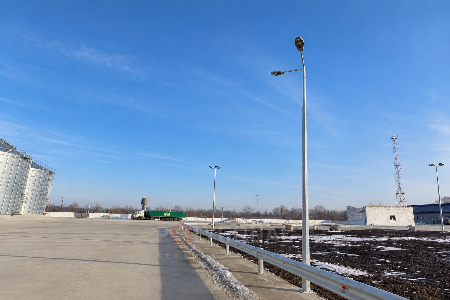
What individual design of outdoor lighting poles, floodlight masts and their foundations involves.
Contents
Input data for design
A standard pole or mast often falls short of what a customer needs to light a particular area. Every area has its own specifics, and the support structure has to be changed to suit them. Individual design takes all of it into account, from the look and number of the attached fittings to how the pole will be erected.
Poles, masts and their foundations are designed with the following taken into account:
- the results of geotechnical surveys for the construction;
- the seismicity of the area;
- what the poles and foundations are for, their structural and process features, and the conditions they will operate in;
- the loads on the support structures and foundations;
- existing buildings and how the new construction affects them;
- environmental requirements;
- the size of the plot available for the pole or mast;
- a technical and economic comparison of the possible design options, to pick the most advantageous one.
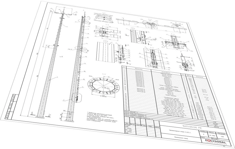
Structural design of the poles
The wall of a steel outdoor lighting pole or floodlight mast is designed to be at least 3 mm thick. The bottom diameter, which is also the flange diameter, is chosen to suit the expected type and size of the foundation.
Depending on the height, a shaft is made of one, two or several sections. A section (the shipping element) is usually no longer than 12 m, so that it is easy to transport.
Sections are joined in one of two ways: a flanged joint, or a slip (telescopic) joint in which one section slides into the next. In a slip joint on bent multi-sided shafts the joint length is taken as roughly one and a half to two section diameters (about 1.8 times the average diameter). Because of the tolerance on slip-joint length at installation, the finished shaft can differ from the design length, and the design takes that into account. The permitted deviation is 10–12% of the joint length.
Slip-joint structures may include parts for drawing the sections together to a tight fit. Where there are none, a winch does the job: the cable runs inside the pole and the load is raised step by step, the step size depending on the section diameter, until the sections stop moving against each other.
Flanged joints on bent multi-sided poles have the bolts set on a circle or around a rectangle. They are used both between sections and at the foundation. With a flanged joint, the shaft height achieved at installation matches the design value exactly.
Poles and masts can be fitted with ladders and platforms for servicing floodlights. The ladders have guards or a fixed fall-arrest system, and there are rest platforms no more than 10 m apart. Ways of climbing the poles are covered in a separate article.
Structural design of the poles
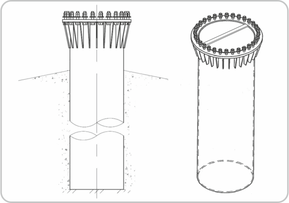
Foundation design
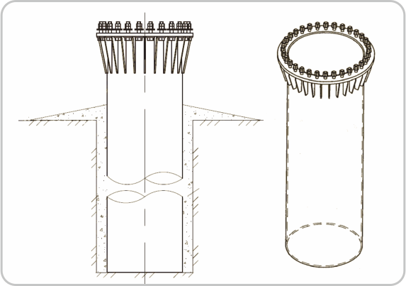
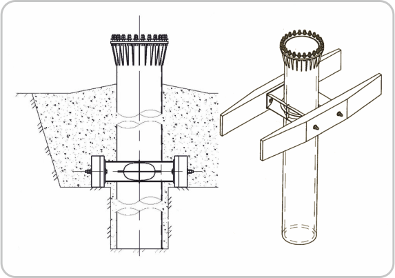
We design the foundations for lighting poles and floodlight masts as well. Each solution is individual, set by the soil conditions and the load from the particular pole. Among the most common are:
- single steel pile shells;
- single bored piles;
- piled foundations on screw piles with a steel grillage;
- piled foundations on steel pile shells with a steel grillage;
- foundations with a cast-in-place reinforced concrete grillage on screw, driven or bored piles or steel pile shells;
- cast-in-place foundations.
The pile variants are a pile shell, a pile shell reinforced with two crossbars, a vibro-driven pile shell and a bored pile. There are also multi-pile bored foundations and cast-in-place or steel grillages with screw piles. The article on lighting pole foundations covers the simplest options and how they are built.
What in the input data affects the design
Every item of input data changes something in the design of the pole. Read about wind regions in Wind Regions of Ukraine and about foundation types in Lighting Pole Foundations.
| Input data | What changes in the structure |
|---|---|
| Wind region, windage of the equipment | shaft diameter, wall thickness, load on the foundation |
| Mass and position of luminaires | load at the top of the shaft, moment at the base |
| Soil conditions from the geotechnical survey | foundation type (piled or cast-in-place) and its dimensions |
| Pole height | number of sections, type of joint, flange, anchors |
| How the pole is serviced | ladders and platforms, guard rails or a fall-arrest system, a fixed or lowering head frame |
| Cable connection | size and position of the hatch for connecting the cable |
Example: sections, joints and height deviation
A section is usually no longer than 12 m. In a flanged joint the section lengths add up to the shaft height, while in a slip (telescopic) joint neighbouring sections overlap, so their sum exceeds the height by the total length of the joints.
An illustrative example with assumed values. The average diameter at the joint is 0.4 m (taken as equal for every joint for simplicity; in a real pole the diameter decreases towards the top, so the joint lengths differ); the joint length is taken as about 1.8 average diameters, that is 1.8 × 0.4 = 0.72 m; the maximum section length is 12 m. The permitted deviation is 10–12% of the joint length (see the section “Structural design of the poles”); at the upper limit it reaches 0.72 × 12% ≈ 86 mm per joint.
| Shaft height | Flanged joint | Slip joint | Height deviation (slip joint) |
|---|---|---|---|
| 12 m | 1 section | 1 section | no joints |
| 20 m | 2 sections | 2 sections, 20.72 m in total | up to 86 mm |
| 24 m | 2 sections of 12 m | 3 sections, 25.44 m in total | up to 173 mm |
| 30 m | 3 sections | 3 sections, 31.44 m in total | up to 173 mm |
For 24 m, two 12 m sections give only 24 m, while with a slip joint the sections must total 24.72 m, so with a 12 m limit per section three are required. The deviation shown is the worst case, where the errors of the joints have the same sign: for two joints, 2 × 86.4 ≈ 173 mm. A flanged joint gives the design height; for 24 m this is a limiting case: both sections must be exactly 12 m, with no margin at all, so in practice the split is checked against the drawing. The actual dimensions are set by the calculation and the KM and KMD drawings.
Typical mistakes in the technical specification
- equipment added later (cameras, antennas, banners) is not in the specification: the windage grows, while the shaft and anchors were calculated with no margin;
- the foundation and the pole are designed separately, and the flange holes do not match the cage anchors (see Foundation Anchor Cages);
- the details were not designed with galvanising in mind: the welded joints have “pockets” and cavities where acid or molten zinc can flow in (Designing Steel Structures for Hot-dip Galvanising);
- the height was chosen by eye, without a lighting calculation (How to Choose the Height of a Lighting Pole).
The technical specification form on this page helps avoid some of these problems: it collects data on height, climatic conditions, attached equipment, head frame, ladder, sections and joint type, and we prepare the design documentation for the KM stage on that basis.
Plinth, wiring and earthing of a lighting pole under the PUE
Below are only the requirements the Rules for the Arrangement of Electrical Installations (PUE), 2026 edition, place on a project; for a specific site the designer takes the final values from the current text.
Under PUE (2026 edition), cl. 6.3.32, the cable entry into a pole must be confined to the plinth. The plinth must be large enough for the cable branching and the fuses or circuit breakers on the branches to the lighting fittings, and have a lockable door for servicing. Special entry boxes on poles are also permitted. The clause names no plinth height or door size.
Wiring inside external-lighting poles is made with insulated wires in a protective sheath or with cables; inside poles shared with the contact network of electrified city transport, cables insulated for at least 690 V are used (cl. 6.3.33).
Earthing: where external lighting fittings are protectively earthed, reinforced-concrete and metal poles, as well as wire ropes, must be connected to the PE conductor in networks with an isolated neutral and to the PEN conductor in networks with an earthed neutral (cl. 6.1.48). See Grounding Metal Lighting and Line Poles.
Cabinets: under cl. 1.7.94 (installations up to 1 kV in solidly earthed neutral networks), any metal cabinet with electrical equipment on a building facade or an overhead-line pole that is operated directly from ground level must be connected to the PE conductor of the installation and to a conductor of the equipotential bonding system. That conductor is buried 0.5–0.7 m deep, 1 m from the cabinet (black steel, diameter at least 10 mm); under an asphalt or concrete ground surface, burying it can be omitted. The clause names a facade and an overhead-line pole; it does not say whether it covers a cabinet on a free-standing lighting pole.
Updated:
Designing lighting poles: frequently asked questions
How thin can the wall of a lighting pole be?
Not less than 3 mm for steel outdoor lighting poles and floodlight masts. That is the design minimum; the actual value depends on the load and the pole height.
How long can one section of a pole be?
Usually 12 m at most, so that it can be transported easily. Taller poles are made of several sections joined with a flanged or slip (telescopic) joint.
Flanged or slip joint between sections: what is the difference?
A flanged joint (bolts on a circle or a rectangular pattern) gives a shaft height that matches the design value exactly. In a slip joint, the joint length is roughly 1.5–2 section diameters, and the permitted deviation is 10–12% of the joint length.
Does a 12 m section fit in the galvanising bath?
In length, yes: the bath measures 13 000 × 1 600 × 3 200 mm (length × width × depth) and a section is usually no longer than 12 m. Width, depth and the clearance needed for hanging the product are also taken into account, especially for large flanges, so we determine its exact position in the bath from the drawing.
Can a camera or antenna be added later to a finished pole?
Only if a margin was allowed for in the original calculation or the pole is recalculated for the new load: every extra item increases the windage and the mass at the top of the shaft, and with them the moment at the base and the load on the foundation. So all attached equipment, even if planned for the future, should be stated in the technical specification from the start.
Questionnaire: technical assignment form
Fill in the form and email it to us: we will prepare the KM-stage design documentation from it and calculate the price. The PDF is handy to print; the DOCX can be filled in on a computer.
Technical assignment form: floodlight mast (lighting pole)
A questionnaire for preparing KM-stage design documentation for a steel polygonal floodlight mast: crown type, floodlights, platforms, ladder.
Related products: Street lighting columns · High-mast lighting · Steel structure design (structural and detail drawings)
Read also: Installation of Multi-sided Poles and Masts · Solar Street Lighting · Power Line Pole Types by Purpose: Suspension, Tension, Angle, Terminal · Cross-arms for 0.4–10 kV Lines: TM and TN Types, Reading the Designation
Get a quote for your requirements
Send us your requirements — we will calculate the price and lead time.