
Home / Products / Foundation anchor cages and bolts / Lighting Pole Foundations: Types and Construction
Foundation anchor cages and bolts
Lighting Pole Foundations: Types and Construction
Three main types of lighting pole foundations, the steps for building them and the conditions to take into account at the design stage.
Contents
Cast-in-place foundation
A cast-in-place reinforced concrete foundation is made on site as a concrete block. The work goes in this order:
- excavating the foundation pit;
- setting up the formwork;
- placing the reinforcement;
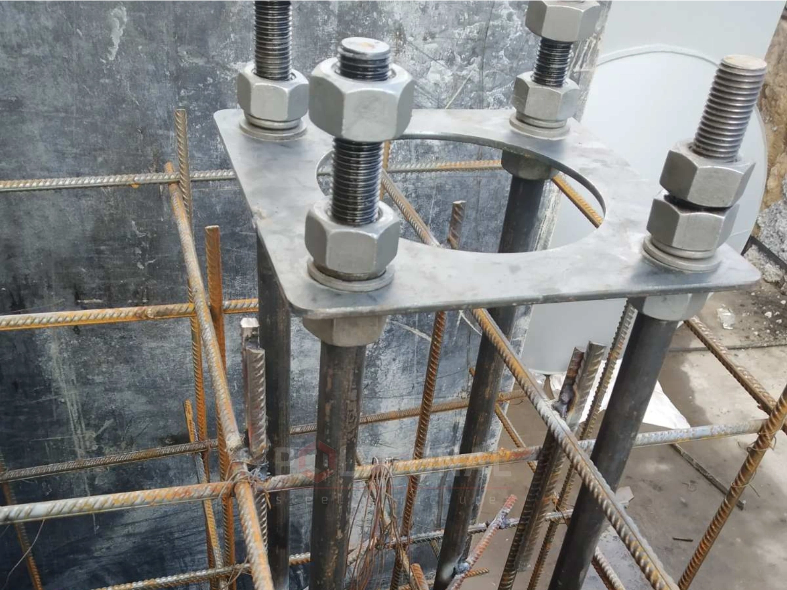
- installing the anchor cage with a template, through which the pole is fixed to the foundation;
- fitting a condensate drain tube;
- running the wiring for the later connection to the power cable;
- pouring the concrete;
- backfilling the pit.
Foundation anchor cages
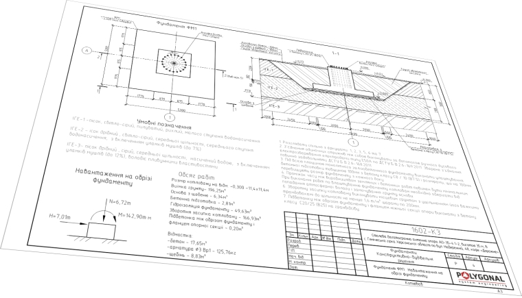
Monolithic foundation: drawing
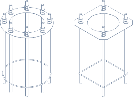
Anchor cage
Pile shell foundation
A foundation of single pile shells is made by lowering a steel pile into a pre-drilled pit and filling it with concrete. The pile shell is made at the factory, usually from a tubular section. The pole is fixed to the foundation by a flange connection. The sequence is:
- drilling a pit 100 mm wider than the diameter of the pile shell;
- placing the pile shell in the pit;
- fitting a condensate drain tube;
- running the wiring for connection to the power cable;
- filling with concrete the inside of the pile and the space between the walls of the pit and the pile.
The drain tube and the wiring are fitted through technological holes in the pile shell.
Precast block foundation
A foundation in the form of a precast concrete block is made by lowering the block into a prepared pit and backfilling it. The block is made at the factory: a reinforced unit with an anchor cage already fitted for fixing the pole and a technological opening (window) for the condensate drain tube and the wiring. Steps:
- excavating the pit;
- placing the concrete block in the pit;
- fitting a condensate drain tube;
- running the wiring for connection to the power cable;
- filling the technological opening with cement-sand mortar;
- backfilling the pit.
Foundation anchor cages
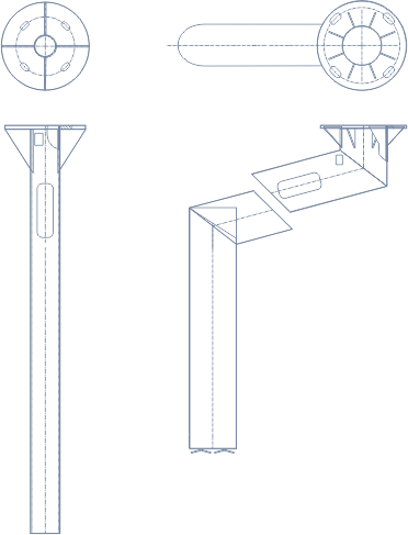
Shell-pile foundation
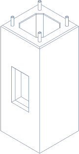
Precast block foundation
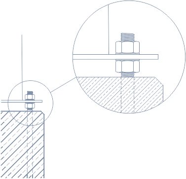
Precast block foundation: joint detail
How foundations are designed
Lighting pole foundations are designed from the customer’s technical specification to DBN V.2.1-10:2018. Under it, foundations are calculated for two groups of limit states: the first for bearing capacity, the second for deformation. The design takes into account:
- the results of geotechnical surveys;
- the seismicity of the construction area;
- the purpose, structural and process features of the poles and foundations and their operating conditions;
- the loads acting on the poles and foundations;
- the existing buildings and the effect of new construction on them;
- environmental requirements;
- the size of the plots;
- a technical and economic comparison of the possible options to choose the most advantageous one.
Which foundation to choose
The choice depends on the soil, pole height, luminaire and wind loads, and the site conditions (schedule, equipment, utilities).
| Foundation type | When it fits | Notes |
|---|---|---|
| Monolithic reinforced concrete | stable soils, tall poles and significant loads | made on site; concrete needs time to gain strength |
| Shell pile | weaker soils, limited space, fast installation needed | factory-made pipe, the pole is fixed with a flange; the hole is drilled, not dug |
| Precast block | tight deadlines, standard low poles | the block is lowered into the pit and backfilled; fewer wet processes on site |
Anchor unit and template
The pole is fixed to the foundation with a flange on anchor bolts. To make the flange holes match the anchors, the bolts are set in a template that fixes their position before the concrete is poured. The template also defines the height of the anchors above the surface and the verticality of the pole after installation.
The power cable enters through a service hole in the foundation (a condensate drain tube); the tube is installed before pouring.
The foundation as an earth electrode: what the PUE says
Under the Rules for the Arrangement of Electrical Installations (PUE), 2026 edition, cl. 1.7.115, reinforced-concrete structures of buildings and facilities that are in contact with the ground may be used as natural earth electrodes, including foundations in non-aggressive, weakly aggressive and moderately aggressive environments. For overhead-line poles the clause separately names the underground parts of reinforced-concrete and metal poles together with their foundations, provided the concrete is not waterproofed with polymer materials. Overhead outdoor-lighting lines are built to the requirements of Chapter 2.4, “Overhead power transmission lines up to 1 kV” (cl. 6.3.26), and that chapter states that a metal pole on a reinforced-concrete foundation must have a metallic bond between its metalwork and the foundation reinforcement (cl. 2.4.33).
The PUE requires four points to be settled by calculation (cl. 1.7.116): whether the current density in natural earth electrodes is acceptable, whether the reinforcing bars of the foundation must be welded, whether the anchor bolts must be welded to them, and whether the foundation may be used at all in a strongly aggressive environment.
An artificial earth electrode of hot-dip galvanised steel buried in the ground must meet the minimum sizes of Table 1.7.5 (cl. 1.7.117). Vertical round electrode: diameter 16 mm, coating 70 µm. Horizontal electrodes: round, diameter 10 mm with a 50 µm coating, and strip, cross-section 90 mm² and thickness 3 mm with a 70 µm coating. Aluminium earthing conductors must not be laid in the ground (cl. 1.7.120). The designer takes the final values for a specific site from the current text of the PUE.
Typical foundation mistakes
- inaccurate anchor position without a template: the pole cannot be seated on the flange without rework;
- insufficient compaction of concrete and backfill, damaged reinforcement cover;
- no cable tube or a tube in the wrong place;
- groundwater, heaving soils and frost depth not taken into account;
- installing the pole before the concrete has gained enough strength;
- earthing not done or damaged anti-corrosion coating on the anchors.
What is needed to calculate a foundation
Send the pole data (height, type, number and weight of luminaires), the construction region and, if available, the results of the geotechnical survey. From this we calculate and propose a foundation. A foundation design can be ordered together with the poles.
Updated:
Reviewed by: V.V. Padalka, Chief Project Engineer
Lighting pole foundations: frequently asked questions
Which foundation type should I choose: cast-in-place, pile shell or precast block?
A cast-in-place foundation is made on site and suits any conditions, but takes longer to build. A pile shell or precast block is made at the factory, so it is installed faster. Which one to pick depends on the soil, the load, and the timeline set by the design.
What criteria is a foundation calculated by?
By two groups of limit states under DBN V.2.1-10: the first for bearing capacity, the second for deformation, based on geotechnical survey results and the loads from the specific pole.
Can I order the foundation together with the pole?
Yes, we design and manufacture foundation solutions (pile shells, precast blocks) together with the pole under a single technical specification.
Related products: Foundation anchor cages and bolts · Street lighting columns · High-mast lighting
More on this topic: Foundation Anchor Cages FPO, FPM, FKM: Sizes and Dimensions · Tram and Trolleybus Catenary Masts: Codes and Foundations · Foundations for Masts, Towers and Power Line Poles: Types, Soil, Anchor Cages
Get a quote for your requirements
Send us your requirements — we will calculate the price and lead time.