
Home / Products / Foundation anchor cages and bolts / Tram and Trolleybus Catenary Masts: Codes and Foundations
Foundation anchor cages and bolts
Tram and Trolleybus Catenary Masts: Codes and Foundations
Catenary masts for trams and trolleybuses are designed to the codes for those lines, and the way each mast is fixed to its foundation is chosen to suit the route.
Contents
- Codes for tram and trolleybus catenary lines
- Catenary masts and the PUE: where the rules end
- Two fixing methods: BKMG and BKM
- What determines the foundation choice
- How to read the designation: from a BKM mast to an FKM anchor cage
- Example: the moment from load P and how the anchor cage grows
- BKMG or BKM: comparison by criteria
- Pre-order checklist
Codes for tram and trolleybus catenary lines
Catenary masts are part of a tram or trolleybus line, so they are designed to DBN V.2.3-18:2007 “Tram and Trolleybus Lines. General Design Requirements”. Height, load and spacing are set by the design project of the particular line, which works from those requirements and from the local conditions along the route.
Catenary masts and the PUE: where the rules end
Chapter 2.5 of the Rules for the Arrangement of Electrical Installations (PUE), 2026 edition, which covers overhead power lines above 1 kV up to 750 kV, does not apply to contact networks. Its scope clause (cl. 2.5.1) lists the contact networks of electrified railways, trams and trolleybuses, and also 6–35 kV lines mounted on contact-network poles, among the lines whose construction is governed by special rules, standards and regulations. Chapter 2.4 (lines up to 1 kV) likewise leaves out the contact networks of urban electric transport (cl. 2.4.1). A catenary mast itself is designed to the standards for such lines, covered above, not to the PUE chapters on overhead lines.
The PUE does mention these poles in its chapters on lighting: they may carry luminaires too. Outdoor luminaires may be installed on poles of the contact networks of urban electric transport of every current type, at voltages up to 600 V (cl. 6.3.2). To feed luminaires on contact-network poles of electrified transport at up to 690 V DC, cable lines or self-supporting insulated wires may be laid (cl. 6.3.25). The two clauses give different voltage limits, 600 and 690 V, so the designer checks the limit against the current text.
Where luminaires stand on reinforced-concrete or metal poles of urban electric transport and the supply network has an earthed neutral, the luminaires and poles are connected to the PEN conductor of the line (cl. 6.1.49). Above a tram contact network a luminaire must be mounted at least 8 m above the rail head, above a trolleybus network at least 9 m above the carriageway (cl. 6.3.5).
Shared poles are a separate case. Trolleybus contact wires and the wires of a line up to 1 kV may be hung on the same poles on two conditions: the poles that carry the contact wires must be mechanically strong enough for the wires of the line up to 1 kV, and the distance between the line wires and the bracket or fixing device of the contact-wire support cable must be at least 1.5 m (cl. 2.4.84, item “д”). All of this describes what the PUE requires of a line design; for a specific line the designer takes the final values from the current text.
Two fixing methods: BKMG and BKM
- BKMG: the mast is set straight into the ground, with no flange;
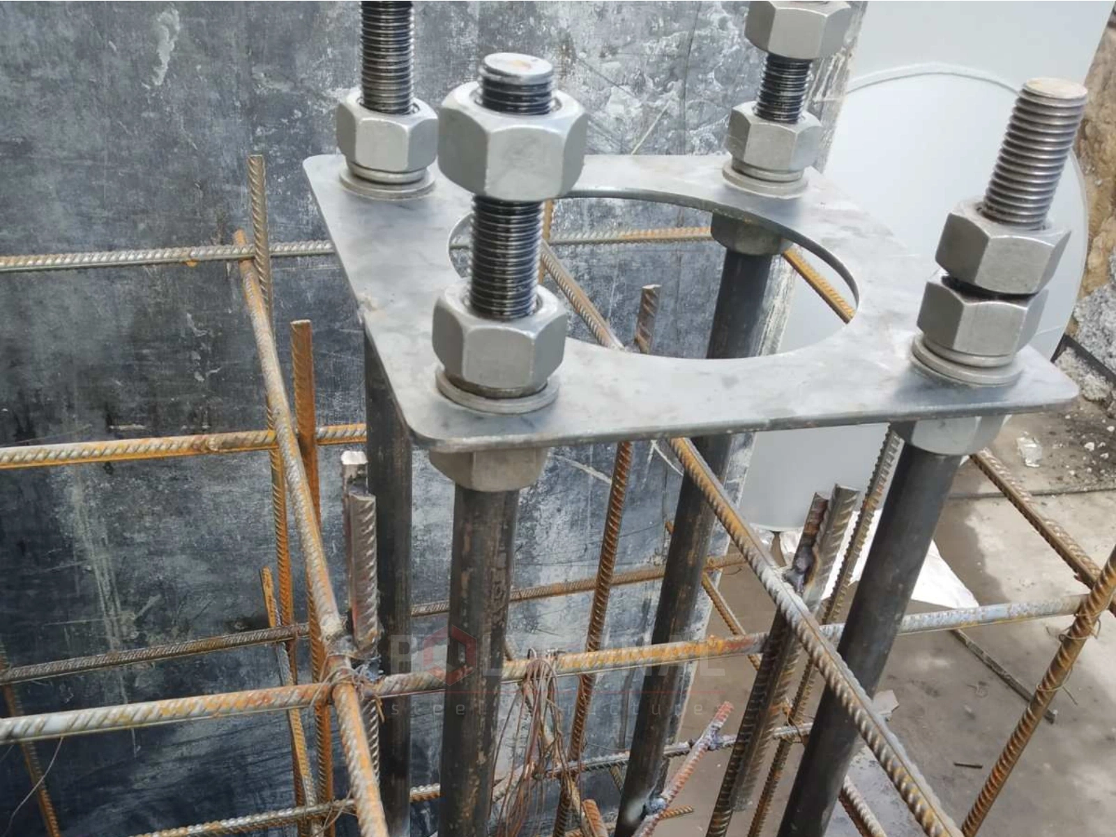
- BKM: an anchor-fixed mast, its shaft attached to the foundation through a flange connection on anchor bolts.
We make both types in heights of 7.3 and 9 m, with design loads from 800 to 2500 kg. The full size table is on the Catenary Masts page.
What determines the foundation choice
- the soil along the route: its bearing capacity decides whether setting the mast in the ground (BKMG) is enough or anchor fixing (BKM) is needed;
- the design load from the overhead wire, plus the insulated cable and lighting if they share the mast;
- frost depth in the region;
- underground utilities on the route.
How to read the designation: from a BKM mast to an FKM anchor cage
Take the BKM-9-15 mast from the catalogue and read the designation part by part:
- 9 is the mast height in metres (the range has 7.3 and 9 m);
- 15 is the load class P, i.e. 1,500 kg. The classes 800, 1,200, 1,500, 2,000 and 2,500 kg are written as 8, 12, 15, 20 and 25;
- for this class the catalogue gives eight M36 anchors and a dimension B = 460 mm;
- anchor cage FKM-460-1040: the first number matches the mast’s B, the second is the cage height in millimetres; anchors 36/8.
For BKM masts 7.3 and 9 m high, the catalogue ties the cage to the load class, not to the height. BKM-7.3-15 and BKM-9-15 share one cage, FKM-460-1040, and the 2,000 and 2,500 kg classes share another, FKM-520-1200. All sizes are in the article on foundation anchor cages.
Example: the moment from load P and how the anchor cage grows
This is a yardstick for comparing classes, not a foundation design. Assume P acts horizontally at 6 m above the ground. The value is only an assumption: the real suspension position and force directions come from the line design.
P is given in kilograms (kilogram-force), so we first convert it to newtons: 1 kgf ≈ 9.81 N. For 1,500 kg the force is 1,500 × 9.81 ≈ 14,715 N, i.e. 14.72 kN, and the moment at the base is 14.72 × 6 ≈ 88 kN·m. The other classes work out the same way:
| Class P, kg | Force, kN | Moment at a 6 m arm, kN·m | Anchor cage and anchors |
|---|---|---|---|
| 800 | 7.85 | 47 | FKM-410-800, 8 × M27 |
| 1,200 | 11.77 | 71 | FKM-450-900, 8 × M30 |
| 1,500 | 14.72 | 88 | FKM-460-1040, 8 × M36 |
| 2,000 | 19.62 | 118 | FKM-520-1200, 8 × M42 |
| 2,500 | 24.53 | 147 | FKM-520-1200, 8 × M42 |
From the lightest class to the heaviest the moment grows 3.1 times (147 against 47 kN·m), and the cage goes from M27 to M42. A real calculation adds wind on the shaft, insulated cable and luminaires on the same mast, safety factors and a soil check. Wind pressure W0 for regional centres is in the article Wind Regions of Ukraine.
BKMG or BKM: comparison by criteria
The fixing type depends on the site. The main differences are in the table.
| Criterion | BKMG (in the ground) | BKM (on a foundation) |
|---|---|---|
| Fixing | the shaft in a prepared pit, no flange | flange on the 8 anchors of an FKM cage |
| What holds the mast | lateral resistance of the soil and of the backfill or concrete around the buried part | the foundation: weight of concrete with backfill and the size of its base, and for piles the soil resistance along the shaft |
| Soil requirements | soil with enough lateral resistance is needed; weak, heaving or waterlogged soil needs a separate check | the foundation is designed for the soil: on heaving soils the base is below the design frost depth or piles are used, and with high groundwater, waterproofing |
| Replacing a mast | usually the pit has to be opened up | unscrew the nuts and set a mast with the same anchor pattern |
The final choice is confirmed by the line design from the survey data.
Pre-order checklist
Have these ready before you send an enquiry:
- where each mast stands on the route: on a straight section, on a curve or as an end mast. Curves and end masts usually take a higher horizontal force than straight sections, so load class P is set for each group separately;
- what else the shaft will carry: insulated cable, a luminaire, a bracket (weight and reach);
- the fixing method (BKMG or BKM), chosen from the table above and the geotechnical survey report. In weak soil it is better not to choose BKMG without a report;
- for BKM, the FKM cage: it follows load class P, not mast height alone;
- where the underground utilities run: this is agreed before the pits are marked out;
- who builds the foundation, and when. A specialised organisation erects the mast once the foundation has gained the required strength (see Installation of Multi-sided Poles and Masts).
Updated:
Catenary mast foundations: frequently asked questions
How is BKMG different from BKM?
BKMG goes straight into the ground and has no flange. BKM is fixed to a foundation: its flange connects to anchor bolts. Which one you need depends on the soil and the design load.
What standard are catenary masts designed to?
DBN V.2.3-18:2007. It governs the design of tram and trolleybus lines, catenary masts included. The parameters of a specific mast come from the line’s design project.
What data do you need to choose a foundation?
Soil type along the route, the design load (overhead wire, insulated cable, lighting), frost depth, and any underground utilities. Send us these and we will select the mast and foundation type.
Is the FKM cage chosen by mast height or by load?
By load class P, not by height. In the catalogue BKM-7.3-15 and BKM-9-15 share one cage, FKM-460-1040 (8 M36 anchors), and the 2,000 and 2,500 kg classes use FKM-520-1200 (8 M42 anchors). That holds for BKM masts 7.3 and 9 m high; the foundation as a whole is still checked for the specific mast.
Can I choose a higher load class for a safety margin?
You can, but a higher class usually brings a different cage and larger anchors: for example, M36 becomes M42 between the 1,500 and 2,000 kg classes. The exception is the 2,000 and 2,500 kg pair, which share one cage, FKM-520-1200. The foundation will probably grow too, so set class P from the load in the line design (in the catalogue P is the standard load), not at random.
Related products: Foundation anchor cages and bolts · Catenary masts
More on this topic: Foundation Anchor Cages FPO, FPM, FKM: Sizes and Dimensions · Lighting Pole Foundations: Types and Construction · Foundations for Masts, Towers and Power Line Poles: Types, Soil, Anchor Cages
See also: Steel multi-sided catenary masts
Get a quote for your requirements
Send us your requirements — we will calculate the price and lead time.