
Home / Services / Steel structure design (structural and detail drawings) / KM and KMD Drawing Rules: DSTU, Specification, Scales
Steel structure design (structural and detail drawings)
KM and KMD Drawing Rules: DSTU, Specification, Scales
How working drawings of steel structures are prepared under DSTU 9286:2024: which standard applies, how the shipping element specification is filled in and the mass worked out, and the rules for scales, fonts and dimensions.
Contents
Preparing Drawings under DSTU: Which Standard Applies to KM and KMD
Steel structure drawings are prepared under two national standards of the System of Project Documentation for Construction (SPDB): DSTU 9286:2024, in force from 1 March 2025, and DSTU 9243.4:2023, in force from 1 April 2024.
The table lists DSTU 9286:2024 and the documents it refers to; the design stages and the contents of the sets are covered in KM and KMD Stages: Contents of the Sets. The standard also permits BIM methods; the requirements for the information model are then fixed in the design brief. What each set contains is described in KM drawings and KMD drawings.
| Document | What it contains | Where it matters for KM and KMD |
|---|---|---|
| DSTU 9286:2024 | composition and rules for KM, KMD and KM-KMD documentation: schedules, specifications, views, dimensioning | the main standard for steel structure drawings |
| DSTU 9243.4:2023 | basic requirements for project documentation, including title blocks and sheet frames | requirements for every sheet and for the whole set; DSTU 9286:2024 refers to it |
| DSTU 9243.7:2023 | rules for architectural and construction working drawings | taken into account in the layout schemes of structural elements |
| DSTU B V.2.6-177:2011 | symbols (marks) of steel building structures | the letter abbreviation (column, beam, truss) and the serial number in an element mark |
| DSTU EN ISO 2553:2022 | symbolic representation of welded joints on drawings | the recommended way of marking welds in KMD and KM-KMD |
Before relying on a standard, check its status in the catalogue of the national standardization body: editions get replaced.
KM, KMD drawings
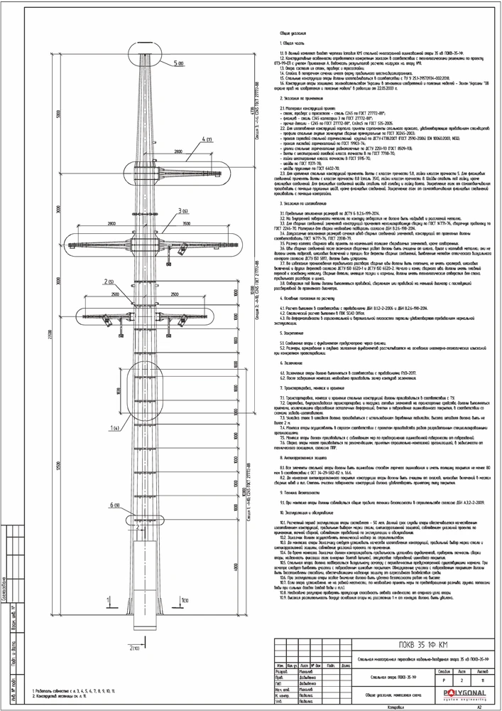
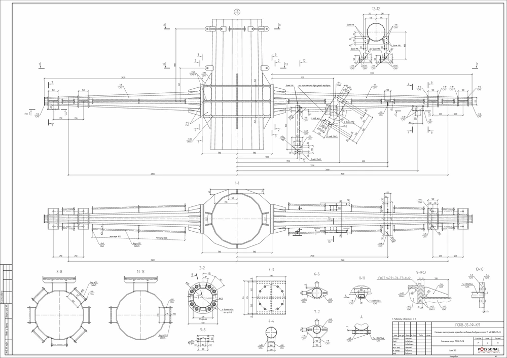
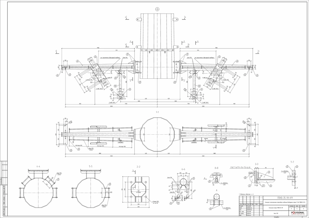
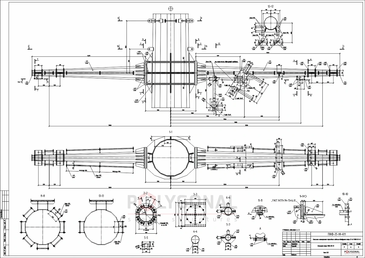
ESKD or DSTU: Which Rules Govern KM and KMD Drawings
ESKD, the Unified System for Design Documentation, is not the basis for KM and KMD drawings: they follow SPDB, that is, DSTU 9243.4:2023 and DSTU 9286:2024. ESKD grew out of Soviet GOST standards and was written chiefly for documentation of mechanical engineering and instrument-making products, while SPDB covers project documentation for buildings and structures.
The previous SPDB series of 2008–2009 relied on Soviet GOST standards, and most of them have since been cancelled in Ukraine. In the new 9243 standards, references to GOST standards that lost force have been replaced with harmonised DSTU ISO and DSTU EN ISO standards.
The shipping element specification
The working drawings of shipping elements carry a specification. The standard recommends placing it on the right-hand part of the sheet; in its worked examples it sits at the top right. It gives:
- “Element mark”: the letter and number designation of the element’s mark;
- “Part no.”: the numbers of the parts used in the drawings of the element, in ascending order, without the “t” and “n” indices; the numbers on the images and in the specification must match;
- “Qty, pcs”: the number of parts; mutually mirrored parts are marked with the indices “t” (from так, “as drawn”) and “n” (from навпаки, “the other way round”), and the standard also permits continuous part numbering without these indices;
- “Section”: the symbol and size of the rolled profile the parts are designed from;
- “Length, mm”: the length of the parts; for flat plate parts, the longer side of the circumscribed rectangle, whatever the shape of the part;
- “Mass, kg”: the mass of one part, the total for all parts and the mass of the element as a whole;
- “Metal name or grade” and “Note” (extra instructions on process operations such as bending, milling or chamfering).
Bent parts have rules of their own. The length of bent plate parts, bent angles and channels is taken along the line through the centroid of the section; for an I-beam bent in the plane of least stiffness, along the beam axis; for parts of closed bent-and-welded profiles of square and rectangular section with oblique cuts at the ends, as the longer side of the circumscribed rectangle. The specification gives final sizes after all process operations. Allowances and shrinkage are not shown on the drawings, because the manufacturer’s process documentation sets them.
For the mass calculation, steel density is taken as 7850 kg/m³. The mass of parts and shipping elements is recommended to be worked out and stated to 0.1 kg, rounded up. Plate parts with straight or curved edges are calculated from their actual area; a part that fits inside a rectangle of up to 0.2 m² may instead be calculated from the area of that rectangle. For parts of shaped section, the theoretical mass per unit length given in the standard for that section is multiplied by the length in the specification. Bolt holes are not deducted from the mass of a part unless the design brief says otherwise.
The mass of an element includes the weld metal of the factory welds, entered on a separate line and taken as 1% of the mass of all the parts of the element, unless the brief for the KMD work sets a different figure. Where the welds weigh more than 1% of the element, the actual mass is recommended instead. Transport and erection elements (lifting lugs or loops, for example) count towards the mass of the shipping mark if they are shown on its drawing.
Main rules for drawing KM and KMD
What follows covers only some of the general rules for preparing working drawings of steel structure elements; for the full requirements, see the current edition of DSTU 9286:2024. The forms, sizes and filling order of title blocks and additional columns, and the sizes of sheet frames, are set by DSTU 9243.4:2023. All inscriptions in a set are made in one style and font; check sheet formats and line types against the standards in force. Recommended font sizes, in mm, are 2.5 and 3.5 for text notes and explanatory labels beside images of structures, elements and parts; 3.5 and 5 for the names of images (layouts, sections) and for headings in text notes and schedules; and 3 for tables.
Scales are chosen to suit the complexity of the images, so that the drawings are convenient to use. The recommended series are: element layout schemes, general-view drawings, sections and geometric schemes — 1:50, 1:100, 1:200, 1:400; joints of structures — 1:5, 1:10, 1:15, 1:20; shipping elements and parts in KMD — 1:10, 1:15, 1:20, 1:25, 1:50; joints of parts (edge preparation and the like) — 1:1, 1:2, 1:5. KMD erection diagrams must match the layout schemes of the KM drawings.
Structures and elements may be shown schematically (conventionally, as a single line), in detail, or in a combination of the two. Schematic or combined drawing is recommended for general-view and layout schemes, while joints, shipping marks and parts are drawn in detail; in a detailed image, visible parts are drawn with a solid line and hidden parts that adjoin visible ones with a dash-dot line. In KMD the main view of a shipping element must match its working position: horizontal elements are drawn horizontally, vertical ones vertically. Long vertical elements (columns, posts) and sloping ones may be laid out horizontally on the sheet; for vertical elements laid out that way, the elevation marks of the top and bottom are given.
To cut the volume of drawing work, an element may be shown up to its axis of symmetry and images may be combined: elements with the same image and section that differ in dimensions or in the placement of parts and holes may share one image, but elements whose main parts have different sections may not. Complex and lattice shipping elements, such as trusses and lattice columns, need a geometric scheme. Rolled and bent elements and parts are shown viewed from the outside, with a development (flat pattern) added: for a rolled part the radius and rolling direction are given, for a bent part the bend line, radius, angle and bend direction. Check the arrangement of views and the marking of viewing directions against the standards in force.
All dimensions are in millimetres. By purpose they fall into erection dimensions (the position of the structure on site), linking dimensions (the step from erection dimensions to those for fabrication), dimensions for making the parts, dimensions that fix how parts sit relative to each other during assembly, and check dimensions for elements. Element dimensions are tied to the axes of the building or structure or to the axes of adjoining elements. A run of identical dimensions may be written as n × b = B, where n is the number of dimensions, b the value of one and B their sum: 5 × 6000 = 30000.
Dimensions across the height or width of rolled sections (angles, I-beams, channels) are given without closing the dimension chain and are referenced to the plane or face that fixes the position of the element in the structure; the gauge lines of rolled and bent angles are referenced to the back of the angle. For an angle with unequal legs, the size of one leg is given, the larger one by recommendation, to fix the position of the angle. The letter R goes before a radius size, and the dimensions of the outline of a curved profile and of large-radius arcs are recommended to be given by coordinates.
Updated:
Reviewed by: V.V. Padalka, Chief Project Engineer
KM and KMD drawing rules: frequently asked questions
Which DSTU should I follow when preparing KM and KMD drawings?
The main one is DSTU 9286:2024, the rules for design and working documentation of metal building structures. Title blocks, sheet frames and the general requirements for the set come from DSTU 9243.4:2023. The other documents are collected in the table above.
What are the main drawing rules under DSTU for steel structures?
One style and one font are used across the whole set, and the conventional symbols adopted in the project are shown on the “General data” sheet. Elements get letter-and-number marks (К1, Б2, ФП1), and in KMD a KMD serial number is added to the mark (К1-3). Welds are shown either by the table of conventional symbols (recommended for KM) or under DSTU EN ISO 2553 (recommended for KMD and KM-KMD).
Are KM and KMD drawings prepared under ESKD?
No, SPDB applies: DSTU 9243.4:2023 and DSTU 9286:2024. Why ESKD is not the basis here is explained above.
What steel density should I use to calculate part mass?
7850 kg/m³. The mass of parts and shipping elements is recommended to be worked out and stated to 0.1 kg, rounded up.
How much should I add for the mass of weld metal?
1% of the mass of all the parts of the element, unless the brief for the KMD work sets a different figure. It is weld metal and goes on a separate line in the shipping element specification. If the welds weigh more than 1% of the element, the actual mass is recommended instead.
Related products: Steel structure design (structural and detail drawings)
More on this topic: KM Drawings: Contents, Stages, Calculations · KMD Drawings: Contents, Benefits, Cost · KM and KMD Stages: Contents of the Sets · Steel Structure Calculation: Methods and Checks
Get a quote for your requirements
Send us your requirements — we will calculate the price and lead time.