
Home / Services / Steel structure design (structural and detail drawings) / KM and KMD Stages: Contents of the Sets
Steel structure design (structural and detail drawings)
KM and KMD Stages: Contents of the Sets
The design stages for steel structures, the stage at which KM and KMD appear, and what goes into each set. The drawing rules and the shipping element specification are covered in a separate article.
Design stages and working documentation
Steel is valued for its high load capacity and reliability. Steel structures are lighter than, say, reinforced concrete ones and easier to transport, and they are made at specialist factories, which leaves only highly mechanised erection on site. There are two weak points. Steel is prone to corrosion, so it needs special protection such as hot-dip galvanising. And it has poor fire resistance: above 400 °C the material begins to creep. Steel is used for the frames of industrial and civil buildings, bridges, telecom masts and towers, lighting and power line poles, oil storage tanks, gas holders, pipelines and much else.
The design stages are set by DBN A.2.2-3:2014. For KM, DSTU 9286:2024 “Rules for the execution of design and working documentation of metal building structures” distinguishes the stages “design” (P), “working design” (RP) and “working documentation” (R): it describes the part that is approved for P and RP, and the working documentation for RP and R. Which stages apply, and whether the working documentation is split into KM and KMD or issued together as KM-KMD, is for the customer to set and approve in the design brief.
Fabrication and erection need two sets of working drawings: KM (steel structure drawings) and KMD (detailing drawings). KM is usually prepared by a design organisation. At the P and RP stages the KM documentation has to be sufficient to establish the quantities of the main construction work, materials and structures and the estimated cost of construction. The KM working drawings have to carry enough data for the KMD, the corrosion protection design and the work execution design to be developed from them, and for rolled steel and metal products to be ordered.
KMD is most often prepared by the design department of a fabricator, the KMD department of a design organisation or a specialist detailing firm; structures are fabricated and erected from these drawings. Departures of the KMD from the KM working drawings are not permitted, and where one cannot be avoided it is agreed with the author of the KM.
KM, KMD drawings
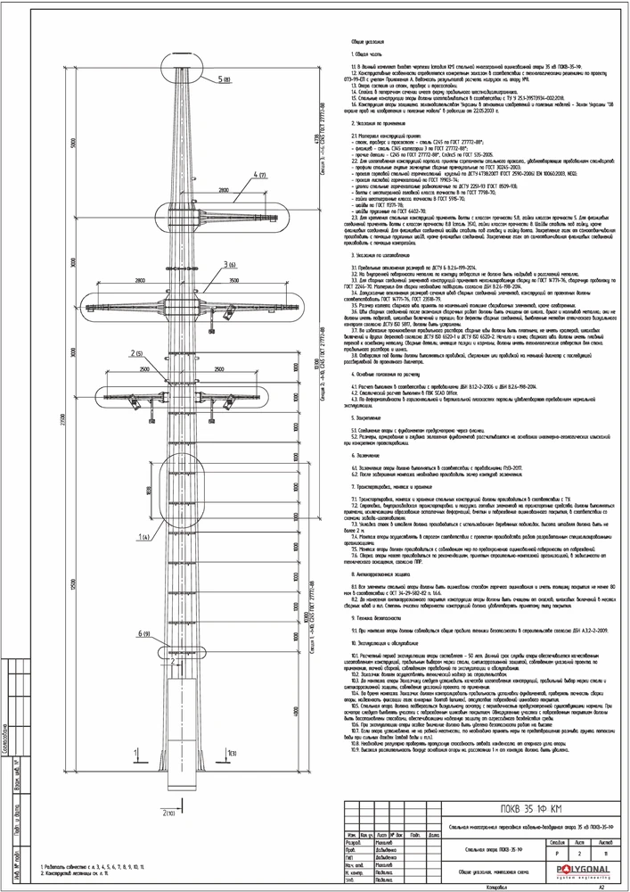
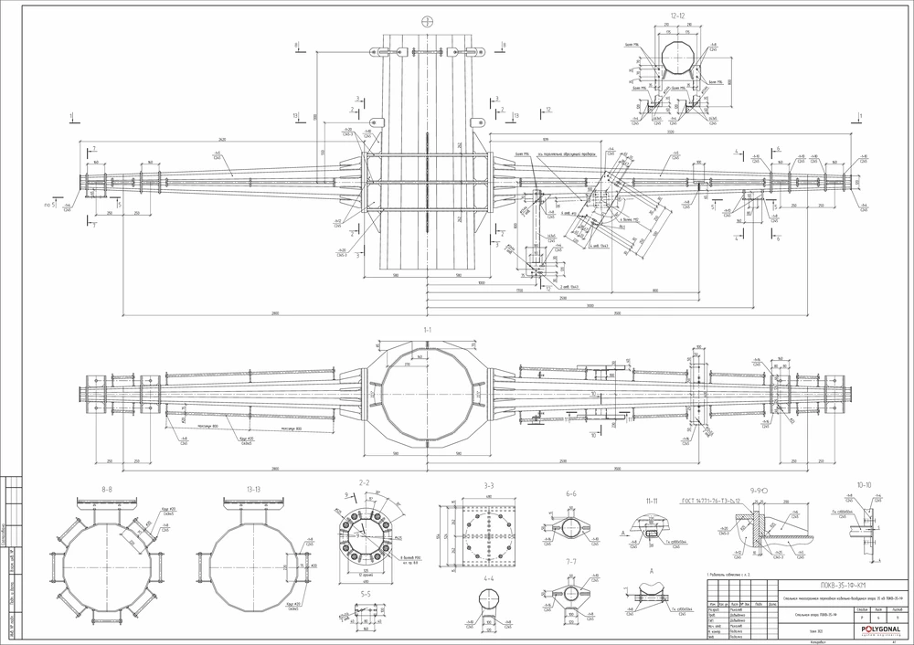
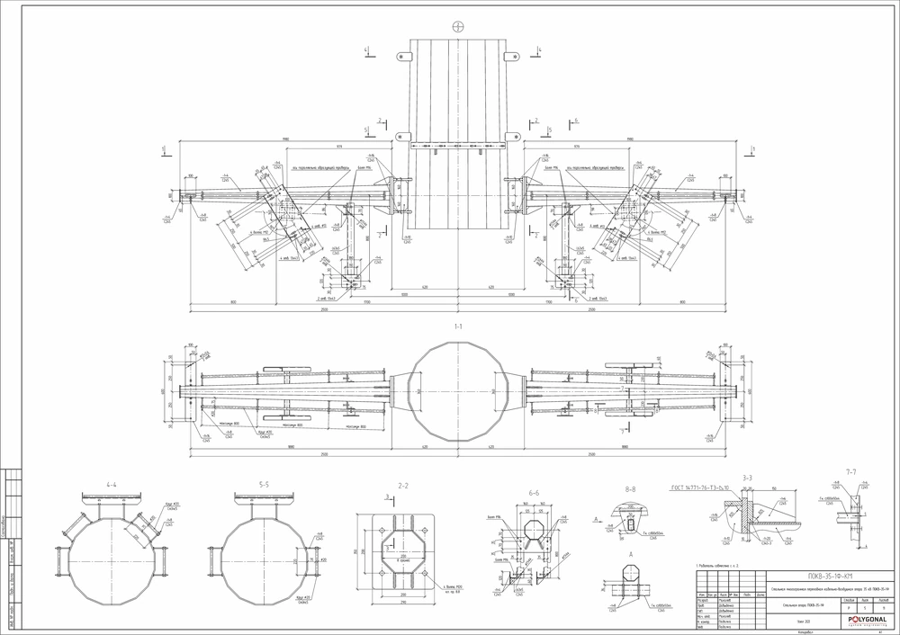
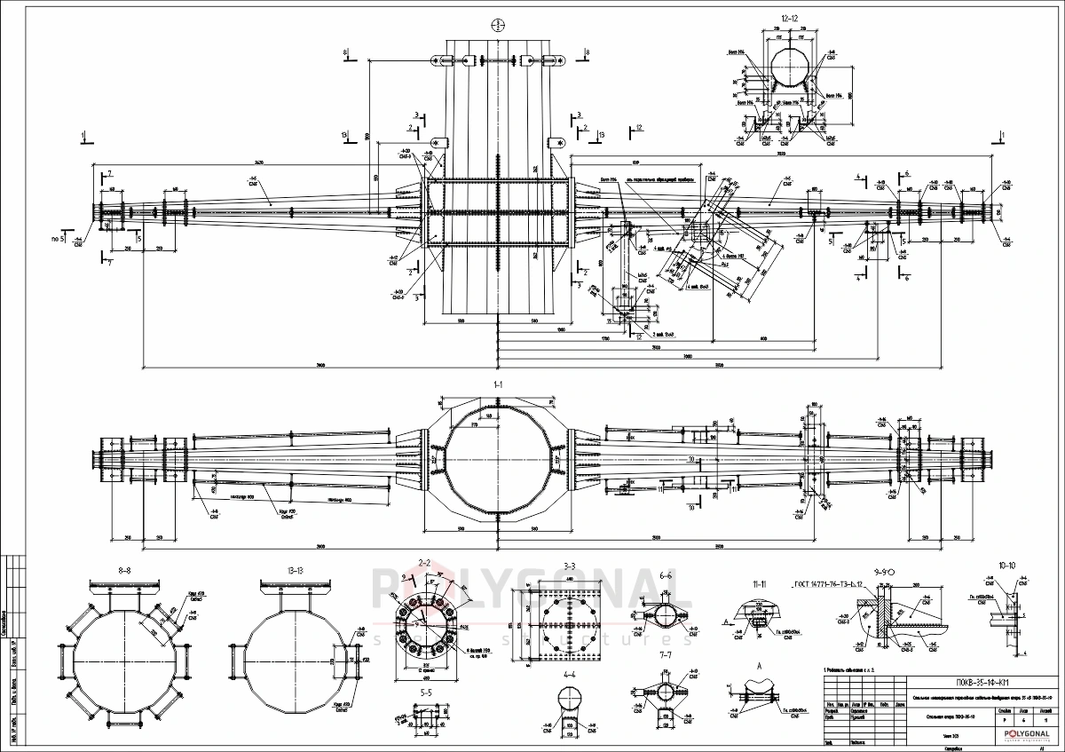
One-, Two- and Three-Stage Design: Where KM and KMD Fit
DBN A.2.2-3:2014, “Composition and content of project documentation for construction” (with amendments), provides for three design schemes: one-stage, two-stage and three-stage. The set of stages in a scheme depends on the consequence class and the purpose of the object (see the table below).
KM appears as early as the project documentation. At the design (P) and working design (RP) stages, in the part that is approved, it consists of an explanatory note and the main drawings. The main KM set belongs to the working documentation of the stages RP and R. KMD is issued as working documentation, on the basis of KM, and in the single-step KM-KMD variant the two are combined in one set. The contents of the sets are described in KM drawings and KMD drawings, and calculations in Steel structure calculation.
| Design approach | Stages | Explanation |
|---|---|---|
| One-stage | RP | a single stage, the working design; its composition and content do not depend on the consequence class of the object |
| Two-stage, objects with minor consequences (CC1) | EP or TER, then RP | EP for non-industrial objects; TER for industrial objects and linear objects of engineering and transport infrastructure |
| Two-stage, objects with medium and major consequences (CC2, CC3) | P, then R | the design; the working documentation is developed after it is approved |
| Three-stage | EP or TEO, then P and R | EP if the object is non-industrial; TEO if it is industrial or linear (engineering and transport infrastructure) |
Abbreviations follow the Ukrainian norm: EP, sketch design; TEO, feasibility study; TER, feasibility calculation (in a shorter form than TEO); P, design; RP, working design; R, working documentation; CC1, CC2 and CC3, consequence classes of the object (minor, medium and major consequences).
Contents of the KM and KMD sets
The main KM set for the stages RP and R contains general data (it is recommended that this sheet give, among other things, the loads and actions assumed for the calculation), the loads that the steel structures transfer to foundations and adjoining structures, a general-view drawing and/or layout schemes of the elements, drawings of joints and a rolled steel specification. A schedule of elements is added where needed. Drawings of individual elements are made only when the layout schemes and the schedule do not define the elements well enough for the KMD to be developed.
The main KMD set consists of general data, summary schedules and specifications, drawings of erection diagrams and joints, and drawings of shipping elements and parts. The summary schedules are the schedule of drawings in the set, the schedule of shipping elements, the rolled steel specification (metal take-off) and the schedule of erection metal products; others are added where needed. Only additional drawings and schedules are produced separately, and again only where needed: cutting drawings for the metal, jigs and fixtures for machining, assembly and welding, transport loading schemes, trial assembly, a schedule of factory welds and so on. They are prepared at the fabricating plant; some are used only in the shop, others on site as well.
On one sheet of the assembly drawing, one or several shipping elements (marks) are shown that have similar sections and common fabrication operations. The drawing contains the elements with dimensions and instructions for assembly, welding of all parts and checking that the assembly is correct; a geometric scheme for complex and lattice elements; the parts assigned to the mark, where they need to be shown; the specification for the shipping element, the schedule of shipping elements, the rolled steel specification (steel take-off) for the element and the technical requirements for making the parts and elements. Where needed, transport elements that keep the shape of the mark during transport and erection, and erection elements such as lifting lugs or loops, are added to the shipping element.
Parts are drawn on the sheets of the shipping elements and/or on separate sheets. A separate part drawing contains the image of the part with dimensions, sections and instructions for making it, the part specification and a list of the shipping marks the part belongs to, with quantities; if the list is not given on the part drawing, a separate schedule is recommended.
Steel structures are fabricated at factories and reach the site by various means of transport, so each structure is divided into shipping elements (marks), parts that are convenient to transport. They usually leave the factory as complete as possible, which cuts the work done on site. Where KM and KMD are done in two successive steps (KM first, then KMD), the KMD author takes into account the requirements set by erection technology (the division into shipping elements, the kitting of parts for assembly) and the manufacturer’s capabilities, if that information is given in the brief for the KMD work, and also calculates the strength of all factory and erection connections that are not in the KM.
How the shipping element specification is filled in, which scales, fonts and symbols DSTU 9286:2024 calls for, and whether ESKD applies are covered in the article KM and KMD Drawing Rules.
Updated:
Design stages for KM and KMD: frequently asked questions
What is the difference between KM and KMD?
KM is usually prepared by a design organisation; the KMD, the corrosion protection design and the work execution design are developed from its drawings, and rolled steel is ordered against them. KMD means detailing drawings from which structures are fabricated and erected; they are made by, for example, the design department of a fabricator, the KMD department of a design organisation or a specialist firm. Departures of the KMD from KM are not permitted; if one cannot be avoided, it is agreed with the author of the KM.
How many design stages are there?
One, two or three, under DBN A.2.2-3:2014. One-stage design is the working design (RP) alone. In two-stage design, objects with medium and major consequences (CC2, CC3) get a design (P) and working documentation (R); objects with minor consequences (CC1) get a sketch design (EP) or a feasibility calculation (TER), then the RP. A three-stage design puts an EP or a feasibility study (TEO) before the stages P and R.
At which stage are KM and KMD drawings made?
KM is present already in the project documentation: at the stages P and RP (the approved part) it is an explanatory note and the main drawings. The main KM set also belongs to the working documentation of the stages RP and R. Where KM and KMD are done in two successive steps, KMD is a separate set of working documentation made on the basis of KM; if the design brief says so, the two are combined into a single KM-KMD set.
Related products: Steel structure design (structural and detail drawings)
More on this topic: KM Drawings: Contents, Stages, Calculations · KMD Drawings: Contents, Benefits, Cost · KM and KMD Drawing Rules: DSTU, Specification, Scales · Steel Structure Calculation: Methods and Checks
Get a quote for your requirements
Send us your requirements — we will calculate the price and lead time.