
Home / Services / Steel structure design (structural and detail drawings) / KM Drawings: Contents, Stages, Calculations
Steel structure design (structural and detail drawings)
KM Drawings: Contents, Stages, Calculations
What KM drawings are, what the set consists of, which stages the work includes and which calculations are made when designing steel structures.
Contents
What KM is and which objects we design
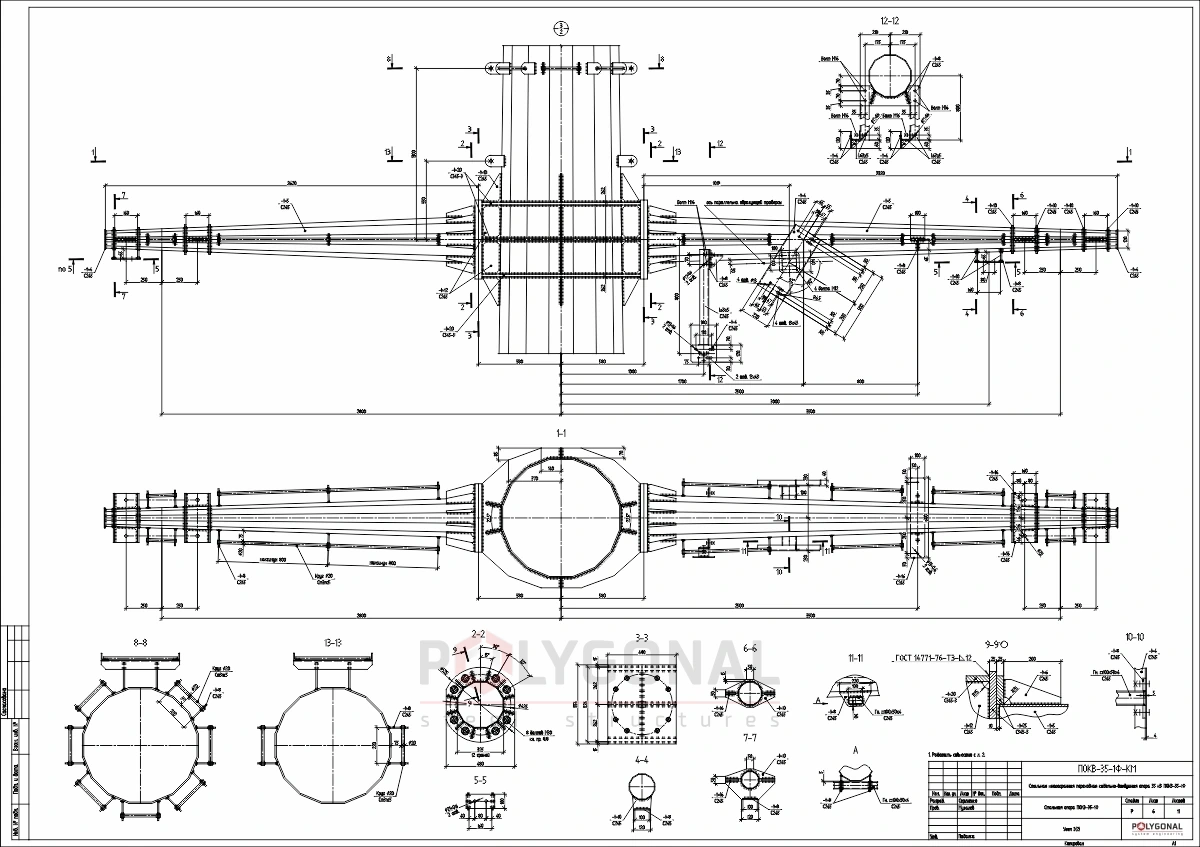
KM stands for “metal structures” (in Ukrainian, конструкції металеві): the structural steel design stage. The engineers of POLYGONAL produce KM drawings of steel structures for various industrial and civil construction sites in a short time. The work is based on a design brief drawn up by the customer and agreed with the designer. Our design engineers have more than ten years’ experience on average, and the design work is done under a responsible lead who has taken continuing training and holds a qualification certificate.
The main areas of KM drawing work are:
- steel structures of power line poles, cellular towers, floodlight masts, antenna supports and other tall tower-type engineering structures;
- structures for process equipment: trestles, galleries, pipelines, flues;
- steel structures of hangars, warehouses and workshops;
- steel structures for industrial and civil use;
- structures of various engineering installations;
- steel structures of water towers and tanks of various capacities.
How we work
We produce KM drawings with modern computers and networked engineering software: several engineers can work at once on one 3D model of a complex structure of any size, so drawings of high quality are issued quickly and with few errors. Building KM drawings are produced by 3D modelling.
We not only produce KM drawings at an affordable price, we also provide the best ratio of cost to quality of the whole job. Besides drawings, we issue information that CNC machines read directly when steel structures are made and that process engineers can use for nesting and for calculating consumption rates. The designers of POLYGONAL follow each of their projects through to completion, up to the erection of the steel structures and often up to commissioning and start of production. Our specialists have taken part in building facilities in power engineering, coke chemistry, metallurgy and other industries.
Contents of the main KM drawing set
The main set of KM working drawings of steel structures includes:
- general data on the KM working drawings;
- data on loads and all actions on the structures;
- data on loads on the foundations;
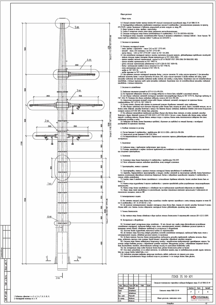
- general-view drawings of the structures of buildings and installations and/or layout schemes of structural elements;
- a schedule of elements (if needed);
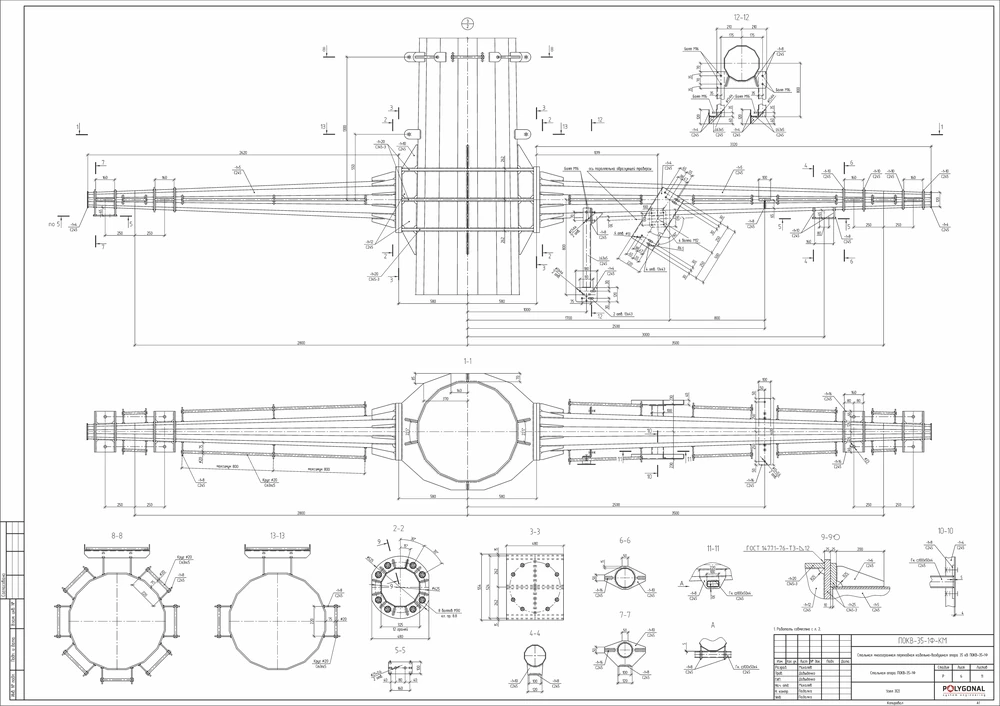
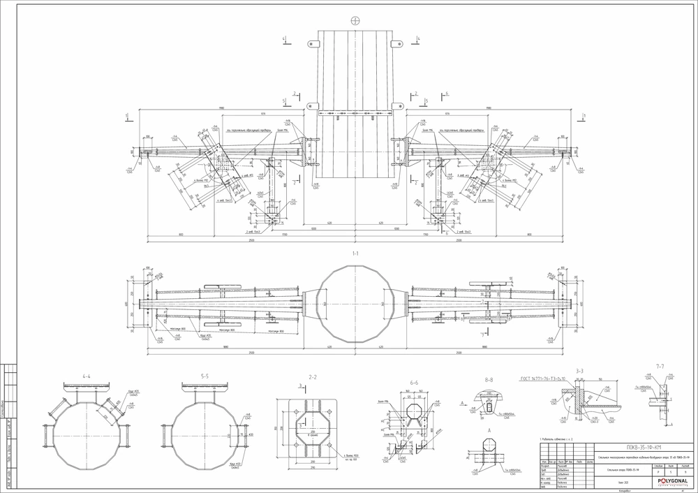
- drawings of structural elements (if needed);
- drawings of structural joints;
- a specification of rolled steel.
Stages of KM drawing work
KM drawing work includes these main stages:
- drawing up and agreeing the design brief;
- an outline scheme as a pre-design solution in the tender documents, with 3D visualisation in specialist software: the customer sees the finished look of the object before the drawings are made and can judge whether it matches the concept and dimensions;
- calculation and selection of the cross-sections of structural elements with specialist software;
- production of KM drawings of the structures and their joints.
Steel structures of buildings and installations are designed to DBN V.2.6-198:2014 “Steel structures. Design standards” and DBN V.1.2-2:2006 “Loads and actions. Design standards”. Calculations are made both by permissible stresses and by two groups of limit states: the first includes states that may lead to loss of load capacity or complete unfitness for use, the second states with unacceptable deformation, displacement or deviation that breach normal operation.
KM, KMD drawings
What the calculations consist of
- determining loads and actions: self-weight, wind, snow, wind with ice and seismic loads and so on (loads and actions for non-standard installations, such as high-voltage line poles and switchyard gantries, and those of special origin are calculated to special technical conditions and norms that supplement and refine DBN V.1.2-2:2006);
- static calculation of forces in the elements (by the methods of structural mechanics and strength of materials; for static and dynamic working of the installation);
- checking elements for strength (under normal and shear forces, torque and bending moments);
- checking slenderness and overall and local stability of elements (a deformation check: displacements must not exceed the limits; during manufacture, transport, erection and service of multi-sided pole elements, spatial rigidity, strength, stability and stiffness must be ensured);
- joint calculation: determining plate thicknesses, the number of bolts and the lengths and legs of welds;
- dynamic calculation of frequencies and mode shapes (for dynamic working of the installation).
How KM relates to KMD
Where KM and KMD are done in two successive steps, KMD is produced from KM; departures from the KM drawings are not permitted, and where one cannot be avoided it is agreed with the author of the KM. If the customer says so in the design brief, the two steps are combined into a single KM-KMD set.
What KMD stands for, and a table comparing the two sets, are in KMD Drawings: Contents, Benefits, Cost.
KM, KMD or KM-KMD: what to order
The choice depends on which drawings you already have. Whether KM and KMD are produced separately or as one KM-KMD set is decided by the customer in the design brief.
| What you order | When it fits | What you get |
|---|---|---|
| KM only | A design solution is needed (layouts, calculations, cross-sections, joints) and someone else will do the detailing | A set of KM drawings with a specification of rolled steel |
| KMD only | A complete KM set already exists and working drawings are needed for fabrication and erection | Detailing drawings, specifications and schedules |
| KM and KMD together (KM-KMD) | There are no source drawings: the work must go from calculation to fabrication | A single set that combines the KM and KMD drawings |
The drawing rules for both sets are described in KM and KMD Drawing Rules, and the design stages and the contents of the sets in KM and KMD Stages: Contents of the Sets.
Updated:
KM drawings: frequently asked questions
What does the main KM drawing set include?
General data, data on loads and actions on the structures and foundations, general-view drawings and/or layout schemes of elements, drawings of joints and a specification of rolled steel; a schedule of elements and drawings of individual elements are added if needed.
How much experience do your design engineers have?
More than ten years on average; the design work is done under a responsible lead who holds a qualification certificate.
Which standards are steel structures designed to?
DBN V.2.6-198:2014 “Steel structures” and DBN V.1.2-2:2006 “Loads and actions”, with calculations by permissible stresses and by two groups of limit states.
What is the difference between KM and KMD?
KM shows the structure as a whole; KMD breaks it down by element and part for fabrication and erection. The comparison item by item is in the table in KMD Drawings: Contents, Benefits, Cost.
Can KMD be ordered without KM?
Where the work goes in two steps, KMD is produced from KM, so KM cannot be skipped. KMD alone is ordered when a complete KM set already exists, even one made by another designer. If it does not, KM is done first or the two steps are combined into a single KM-KMD set; which of these applies is set in the design brief.
Related products: Steel structure design (structural and detail drawings) · Telecom masts · Overhead power line masts
More on this topic: KMD Drawings: Contents, Benefits, Cost · KM and KMD Stages: Contents of the Sets · KM and KMD Drawing Rules: DSTU, Specification, Scales · Steel Structure Calculation: Methods and Checks
See also: Greenhouses: design and manufacture
Get a quote for your requirements
Send us your requirements — we will calculate the price and lead time.