
Home / Products / Telecom masts / Design of Telecom Towers and Antenna Masts
Telecom masts
Design of Telecom Towers and Antenna Masts
Polygonal antenna poles, towers and masts for cellular communications, together with their foundations, are designed for the specific conditions. Here is what source data is needed, what features the structure has and what foundations are used.
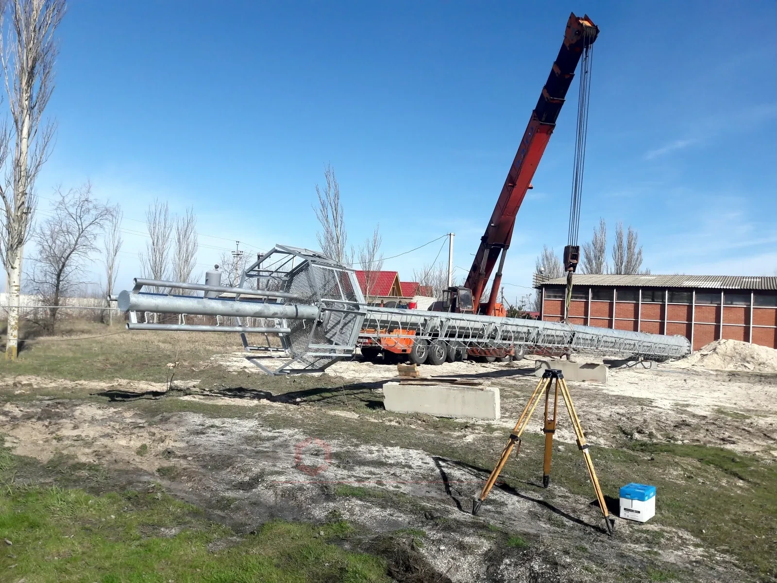
Designing a telecom tower or antenna mast means developing a multi-sided antenna pole, tower or cellular mast together with its foundation, based on geotechnical surveys, the seismicity of the area, the loads and the operating conditions.
Contents
Source data for design
Polygonal antenna poles, towers and masts for cellular communications and their foundations are designed on the basis of, and taking into account:
- results of engineering-geological surveys for the construction;
- the seismicity of the construction area;
- data on the purpose, structural and technological features of the antenna poles and foundations and the conditions of their operation;
- the loads acting on the antenna poles and foundations;
- the conditions of existing buildings and the effect of new construction on them;
- environmental requirements;
- the size of the plot for the antenna pole or mast;
- a technical and economic comparison of possible design solutions, to choose the one that makes the most efficient use of the antenna pole or tower and the foundations.
Structural features of antenna structures
The minimum wall thickness of steel polygonal poles for cellular communications is at least 5 mm. The bottom diameter of the shaft (the flange diameter) is chosen to suit the expected type and dimensions of the foundation.
Depending on the height required, the shaft can consist of one, two or more sections. The maximum length of a section (the length of a shipping element) is usually no more than 12 m, which is convenient for transport.
Sections are joined in two ways: flanged and telescopic. By the type of section joint, antenna structures are divided into poles with telescopic joints and poles with flange joints.
Telescopic joint. The approximate length of the joint depends on the diameters of the sections being joined: it equals one and a half to two diameters (about 1.8 times the mean diameter of the sections). In design, the possible deviation of the shaft length due to the tolerance on the length of the telescopic joint during erection is taken into account; 10–12% of the joint length is allowed. Structures with telescopic joints may have parts to draw the sections together and give a tight fit; if there are none, the sections are drawn together with a winch, with the cable passed inside the mast. It is recommended to draw the sections together under increasing load, in steps that depend on the diameter of the sections, until the sections stop moving relative to each other.
Flange joint. In polygonal poles and towers, flange joints with the bolts placed on a circle or along the outline of a rectangle are used, both at the joints between sections and at the foundation. A flange joint between sections ensures that the height of the shaft obtained during erection matches the design value exactly.
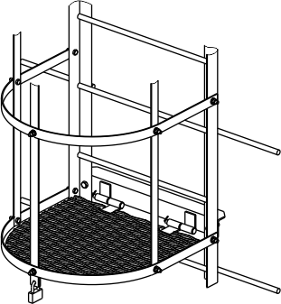
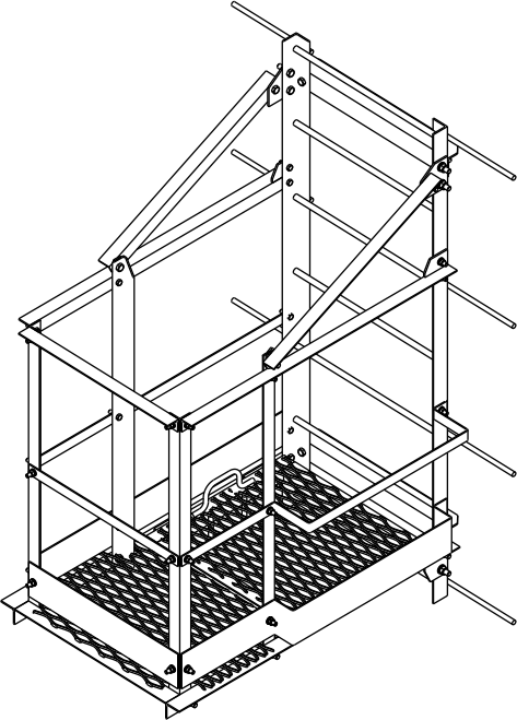
For servicing the antennas and transmitting equipment, poles and masts can have ladders and rest platforms.
Telecom tower design
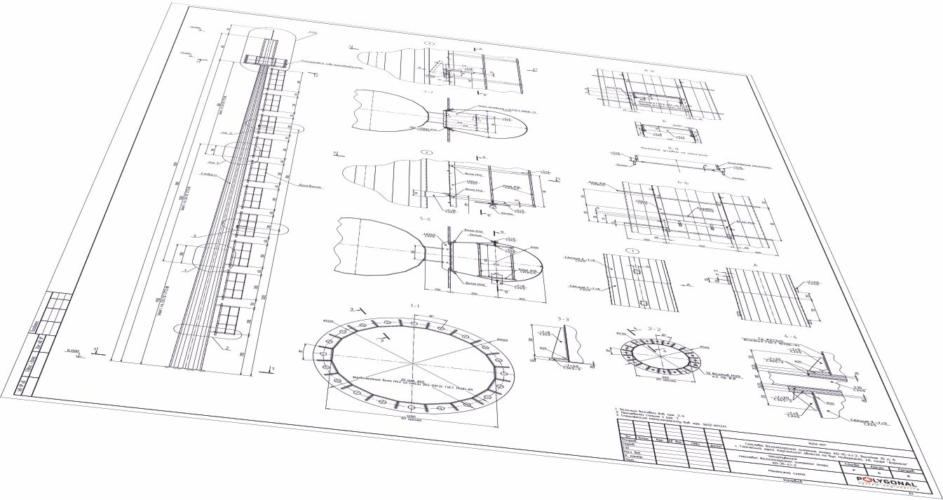
Design of foundations for telecom towers
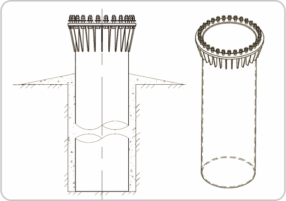
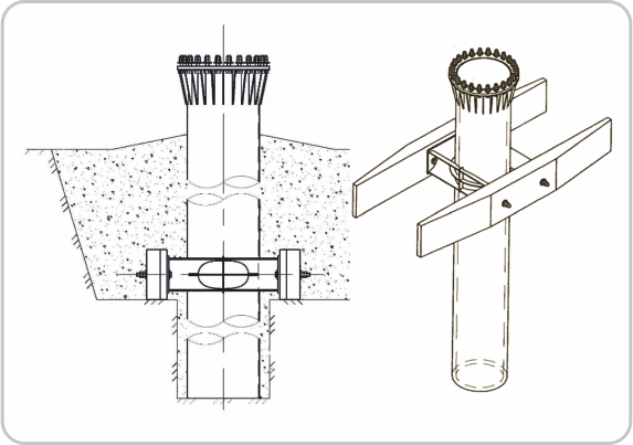
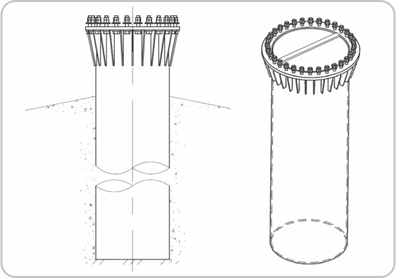
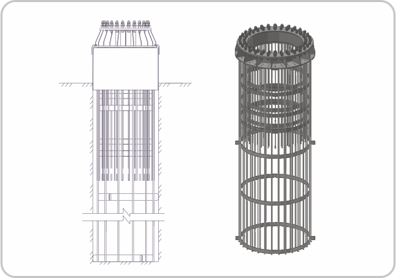
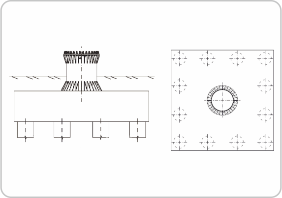
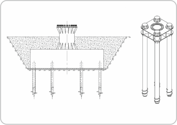
We design foundations for communication towers and antenna masts. Structural and technological solutions for foundations are individual and depend on the specific soil conditions and the load from the specific pole. The most common solutions are:
- from single steel shell piles;
- from single bored piles;
- pile foundations of screw piles with a steel grillage;
- pile foundations of steel shell piles with a steel grillage;
- with a monolithic reinforced-concrete grillage on screw, driven or bored piles, or steel shell piles;
- monolithic.
Shell pile
Shell pile strengthened with two crossbars
Vibro-driven shell pile
Bored pile
Multi-pile bored foundation
Monolithic and steel grillage on screw piles
Foundation options
Loads and checks in tower design
The tower is designed for wind load (taking into account the wind region and height), ice, the weight of the structure and equipment, and antenna loads that depend on the number, area and height position of the antennas. The calculation checks the strength and stability of the elements, the joints of sections and flanges, and the deflection of the tower top: telecom equipment requires limited antenna sway.
Equipment, safety and access
- a technological platform for telecom equipment;
- rest platforms every 10 m with a lockable hatch;
- a caged ladder and an anti-vandal hatch at the start of the ladder;
- if required: lighting fittings, a lightning rod, earth wires, CCTV systems.
What is needed for design and ordering
Send the tower height, the list of antennas (number, size, weight, mounting height), the location and, if available, the geotechnical survey results. You can also fill in the technical specification form for a telecom tower. We prepare the design and foundation and calculate the price and lead time; if needed, installation is carried out by a licensed construction partner company.
Updated:
Designing telecom towers: frequently asked questions
What is the minimum wall thickness of an antenna mast?
At least 5 mm for steel multi-sided cellular masts. The bottom shaft diameter is chosen based on the type and dimensions of the foundation.
What is the maximum section length?
Usually no more than 12 m, determined by ease of transport. Taller masts consist of several sections.
What deviation is allowed on the slip-joint length during erection?
10-12% of the joint length. Sections are pulled together with an increasing load until they stop moving relative to each other.
How does a flanged joint differ from a slip joint?
A flanged joint (bolts on a circle or a rectangular pattern) guarantees the shaft height matches the design value exactly. A slip joint has no such guarantee but is simpler to make.
Questionnaire: technical assignment form
Fill in the form and email it to us: we will prepare the KM-stage design documentation from it and calculate the price. The PDF is handy to print; the DOCX can be filled in on a computer.
Technical assignment form: telecom tower (antenna pole)
A questionnaire for preparing KM-stage design documentation for a steel polygonal antenna pole. Fill it in and send it to us; we will calculate the price and lead time.
Related products: Telecom masts · Antenna masts
More on this topic: Height of a Telecom Mast or Tower: How to Determine It and Choose the Structure · Telecom Tower Types: Multi-sided, Lattice, Guyed Masts · What Is a Mast: How It Differs from a Pole and a Tower, and the Main Types · Cell Tower Explained: What It Is, How It's Built, Typical Heights
Get a quote for your requirements
Send us your requirements — we will calculate the price and lead time.