
Home / Products / Telecom masts / Height of a Telecom Mast or Tower: How to Determine It and Choose the Structure
Telecom masts
Height of a Telecom Mast or Tower: How to Determine It and Choose the Structure
Telecom tower height follows from several inputs: radio planning, terrain, antenna count and loads. We show how it is determined and which structure suits which height.
Contents
- What decides the height of a mast or tower
- Which height classes suit which structures
- Which loads grow with height
- Multi-sided or lattice: which to choose for a given height
- How height affects the foundation and the site
- Approvals and marking: what to find out before fixing the height
- Example: how the height is built up for two operators
What decides the height of a mast or tower
Height is not derived from the coverage radius by a formula: the operator’s radio engineer sets the antenna centre heights, and the designer adds room for the top of the structure and checks the loads. Main factors:
- coverage zone: what must fall within range — a village, a road or an area; line-of-sight range grows roughly as the square root of height, so an antenna twice as high does not give twice the radius;
- terrain: on high ground a lower tower may cover the same zone, while in a hollow a taller one is needed;
- obstacles: buildings, shelter belts, tree crowns; a radio-relay path must clear them with a margin for the first Fresnel zone, and tree growth and new buildings should be allowed for;
- number and levels of antennas: each operator takes a separate level and the radio engineer sets the spacing between levels; spare levels are cheaper to provide from the start;
- top of the structure: above the highest antenna there must be room for a lightning rod and lights;
- the site: size, neighbouring buildings, nearby airfields and power lines.
Which height classes suit which structures
Guidelines from our standard ranges for an initial selection; the final height, sections and foundation are confirmed by calculation for your specification. Mobile extendable masts for temporary deployment are a different product class and are not covered here. The height of lighting poles and floodlight masts is chosen by other criteria: see the article How to Choose the Height of a Lighting Pole and the page Floodlight Masts.
| Height class | Multi-sided tower | Lattice tower (AO) |
|---|---|---|
| up to 25 m | 25 m in the standard range; combined 3G towers of 8 and 12 m; other heights per the technical specification | None: the AO range starts at 29 m |
| 27–45 m | A combined 3G tower of 27 m; 30, 35 and 40 m in the standard range; sections usually no longer than 12 m | AO-29…AO-42.5: base 3.28–5.38 m, total mass 3669.2–8259.9 kg |
| 50–70 m | The standard range ends at 40 m; up to 70 m is an individual design | AO-50…AO-70: base 5.38–7.35 m, total mass 9210.9–19554.6 kg |
Dimensions and loads for each model are on the pages Telecom Masts and Antenna Masts; the differences between types are in the article Telecom Tower Types.
Which loads grow with height
Wind. Speed rises with height and the lever arm about the base increases, so the base moment grows faster than the height, and the required shaft diameter, wall thickness, flange, anchors and foundation grow with it. DBN V.1.2-2:2006 accounts for this with a structure height coefficient and the terrain type. The characteristic wind pressure W0 for regional centres is in the article Wind Regions of Ukraine.
Ice. Ice on antennas, cables and tower members adds weight and wind-catching area; for antenna-mast structures DBN V.1.2-2:2006 requires the combined ice and wind load to be considered. Deposits are heavier on high ground and near large bodies of water. Wind and ice mechanics, using power lines as the example, are covered in the article Loads on Overhead Lines and Transmission Poles.
Equipment. Antennas (radio-relay dishes included), cables, platforms and ladders add weight and windward area; for narrow-beam antennas the allowable deflection of the top is set by the equipment manufacturer. Our standard multi-sided towers show how height, wind and antenna area combine:
| Height, m | Equipment mass, kg | Equipment area at 400 Pa, m² | Equipment area at 600 Pa, m² |
|---|---|---|---|
| 25 | 340 | 3.4 | 1.4 |
| 30 | 200 | 3.0 | 1.0 |
| 30 | 320 | 3.2 | 1.2 |
| 35 | 300 | 3.0 | 1.0 |
| 40 | 300 | 2.8 | 0.8 |
Data from the page Telecom Masts: the maximum equipment area in a wind region with the corresponding pressure. The values for 450, 500 and 550 Pa are given on the same page; for an intermediate pressure take the next higher column, and below 400 Pa use the 400 Pa column. For a larger area the structure is calculated separately.
Multi-sided or lattice: which to choose for a given height
The type of structure is the second decision after height:
- base: a multi-sided tower stands on one foundation, with a flange hole spacing of 840–1230 mm for towers of 25–40 m; a lattice tower has a square base, which in the AO range runs from 3.28 m (AO-29) to 7.35 m (AO-70) between the axes of the leg base nodes;
- equipment area: our standard multi-sided towers of 25–40 m are designed for 0.8–3.4 m² depending on wind, the AO range for a windward equipment area of up to 12 m² in wind regions 1–4; the series differ, so compare calculations for both;
- wind: the lattice lets the flow through and reduces the load, while a multi-sided shaft has a closed profile;
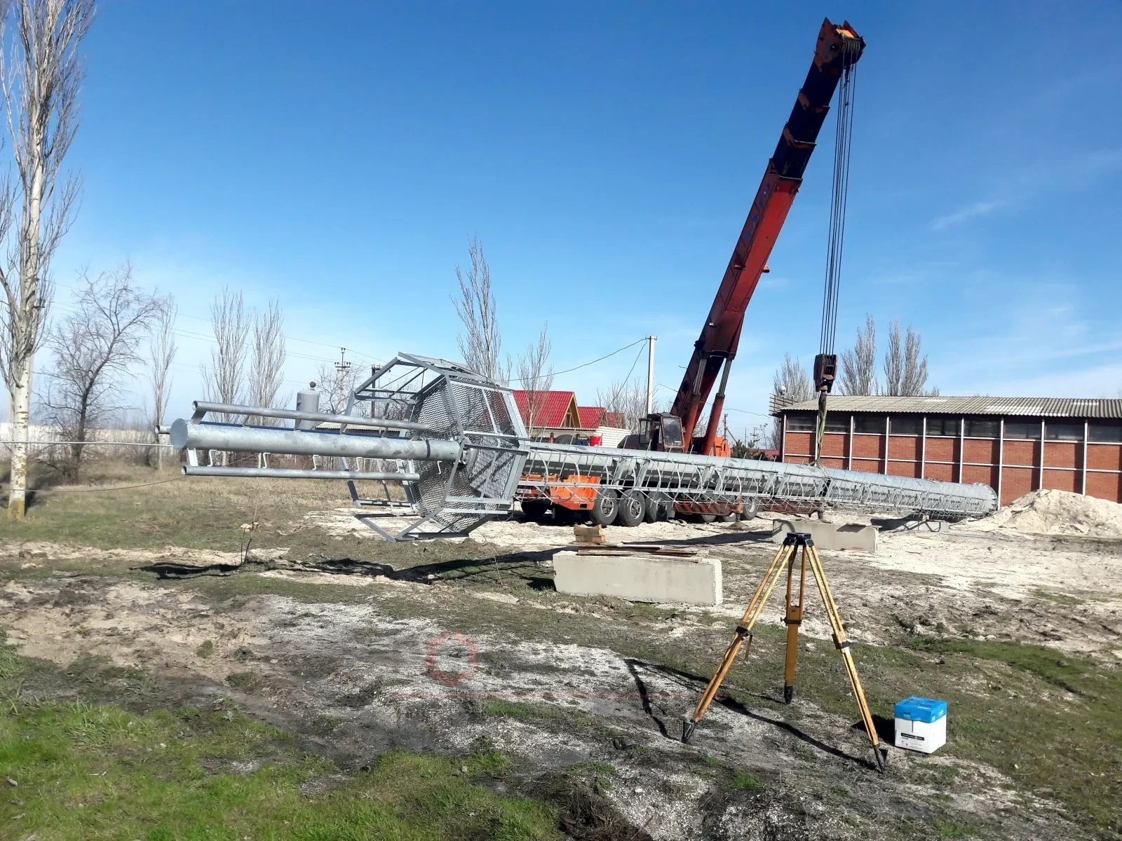
- installation: multi-sided sections are extended vertically or raised whole from the horizontal position, while a lattice tower is assembled from many members.
Up to 40 m and on a tight site, consider a multi-sided tower first; above 40 m, with many antennas or a roomy site, compare it with a lattice tower. At the boundary, calculating both options decides.
How height affects the foundation and the site
The taller the tower, the greater the moment it passes to the base, so the foundation is designed for moment and axial force, not only for weight. In 25–40 m towers from our range the base connection is a flange on anchors: 12 to 20 M36–M42 bolts.
The foundation type for a multi-sided tower depends on soils and load (shell piles, bored piles, a monolithic base), so geotechnical surveys are needed; more in the article Design of Telecom Towers and Antenna Masts. A lattice tower is fixed by a flange on each leg to a monolithic reinforced-concrete foundation; the reinforcement and embedment depth are calculated from the surveys.
The anchor cage is cast in before erection and its anchors must match the flange holes; the principle is shown with cages for lighting poles, floodlight masts and catenary poles in the article on foundation anchor cages.
Approvals and marking: what to find out before fixing the height
A tall structure is also a permitting matter. Whether lighting and daytime marking are needed, what they must be and what height is allowed near airfields and air routes are set by current aviation regulations, with approvals from the relevant bodies. For antenna towers, designs usually provide red-and-white marking and obstruction lights at the top, but the scheme is set each time by height and location. Before fixing the height, find out:
- whether an airfield or an air route is nearby;
- whether there are protection zones of power lines, railways, roads and utilities;
- whether land rights and construction permits are in order.
Example: how the height is built up for two operators
Suppose a tower is to stand at the edge of a village on open flat ground: two operators will cover the village and a stretch of road, and a third may join later.
- the first operator’s radio engineer finds the antenna height at which the line to the farthest point of the zone passes over the shelter belt and a large building with an allowance for crown growth;
- the second operator’s antennas are placed above or below at a spacing set by the radio engineer; the third level is left free, and room for a lightning rod and lights is added above the top one, which gives the height of the structure;
- the result is compared with standard heights: if it falls between two, the larger is taken or the lower antenna levels are agreed; above 40 m the choice is between an individual multi-sided tower and a lattice tower;
- the total windward area is compared with the area allowed for the tower in the wind region, and the site is checked for room for a shaft or base, for suitable soils and for nearby airfields and protection zones.
Updated:
Choosing the height of a tower or mast: frequently asked questions
Can the tower height be found from the coverage radius?
Not by a simple formula: coverage depends on the frequency band, power, antenna tilt, terrain and buildings. The antenna centre height comes from the operator’s radio planning and is the input for our calculation.
Why does a taller tower cost more than its height alone suggests?
Wind load and base moment grow with height, so a thicker wall, a larger diameter, and a heavier flange, anchors and foundation are needed. For lattice towers this shows in the mass: AO-29 weighs 3669.2 kg and AO-70 weighs 19554.6 kg, so the mass grows about 5.3 times while the height grows about 2.4 times. Extra metres kept in reserve have a price.
Can antennas be added or the tower extended later?
A verification calculation of the shaft, joints and foundation is usually needed, because extra height and area increase the base moment. It is easier to build a reserve into the initial calculation.
Are approvals and obstruction marking needed?
It depends on height, location and proximity to airfields, air routes and power lines. Marking and the allowed height are set by current aviation regulations, and construction needs permit documents.
What should I send so you can select the height and structure?
The antenna centre heights from the operator or an approximate height, the number, weight and area of antennas, the location, wind region and terrain type, and survey results if available.
Related products: Telecom masts · Antenna masts
More on this topic: Design of Telecom Towers and Antenna Masts · Telecom Tower Types: Multi-sided, Lattice, Guyed Masts
See also: How to Choose a Flagpole
Get a quote for your requirements
Send us your requirements — we will calculate the price and lead time.