
Home / Products / Brackets, caps and crossarms / Brackets, Crossarms and Caps for Lighting Poles: Types and Marking
Brackets, caps and crossarms
Brackets, Crossarms and Caps for Lighting Poles: Types and Marking
Luminaires and floodlights are fixed to a lighting pole on brackets, with one arm or several. When one pole has to carry a group of floodlights, a cap or a crossarm is used instead. Below are the types available and how to read the mark.
Contents
- KO brackets — for lighting poles
- KP brackets — park type
- OG caps and TR crossarms — mounting several floodlights together
- Material and coating
- How a bracket affects the pole: a UMO-8 example
- KO3 brackets: two arms of different height
- Cap or crossarm: which to choose
- Floodlights on a pole: a check of mass and area
- What to state in a request for a bracket, cap or crossarm
- Bracket reach and pole height
- UMO poles of different heights: allowable luminaire area
KO brackets — for lighting poles
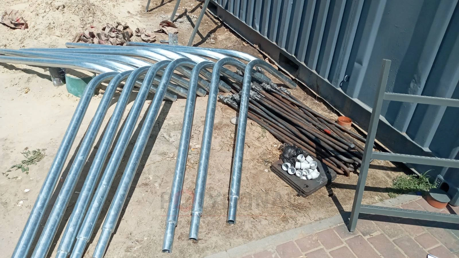
The KO series comes in three shapes: KO1, KO2 and KO3. They differ in geometry and in the number of arms (the luminaire mounting points), from 1 to 4. The catalogue gives a diameter of 48 mm for every mark in the series; it is checked against the pole top and the luminaire seat.
The mark has four parts, read left to right: shape type, number of arms, bracket height (m), bracket reach (m). Example: KO1-2-0.5-1.
| Mark | Number of arms | Height, m | Reach, m |
|---|---|---|---|
| KO1-1-0.5-1 | 1 | 0.5 | 1 |
| KO1-1-1-1.5 | 1 | 1 | 1.5 |
| KO1-2-1-1 | 2 | 1 | 1 |
| KO1-2-1-1.5 | 2 | 1 | 1.5 |
| KO1-3-1-1.5 | 3 | 1 | 1.5 |
| KO1-4-1-1.5 | 4 | 1 | 1.5 |
| KO2-1-0.5-1 | 1 | 0.5 | 1 |
| KO2-1-1-1 | 1 | 1 | 1 |
| KO2-1-1-1.5 | 1 | 1 | 1.5 |
| KO2-2-0.5-1 | 2 | 0.5 | 1 |
| KO2-2-1-1 | 2 | 1 | 1 |
| KO2-2-1-1.5 | 2 | 1 | 1.5 |
| KO2-3-1-1 | 3 | 1 | 1 |
| KO2-3-1-1.5 | 3 | 1 | 1.5 |
| KO2-4-1-1 | 4 | 1 | 1 |
| KO2-4-1-1.5 | 4 | 1 | 1.5 |
Shape KO3 is an asymmetric two-arm bracket with two different heights and reaches (for example, KO3-2-1.1-1: arm heights 1.1 m and 0.6 m, reaches 1 m and 0.5 m); the full list of variants is available on request.
KO brackets
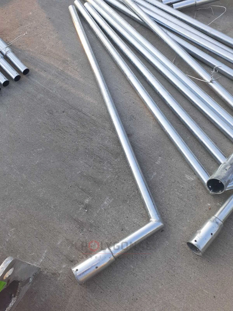
Bracket KO1-0.5-1
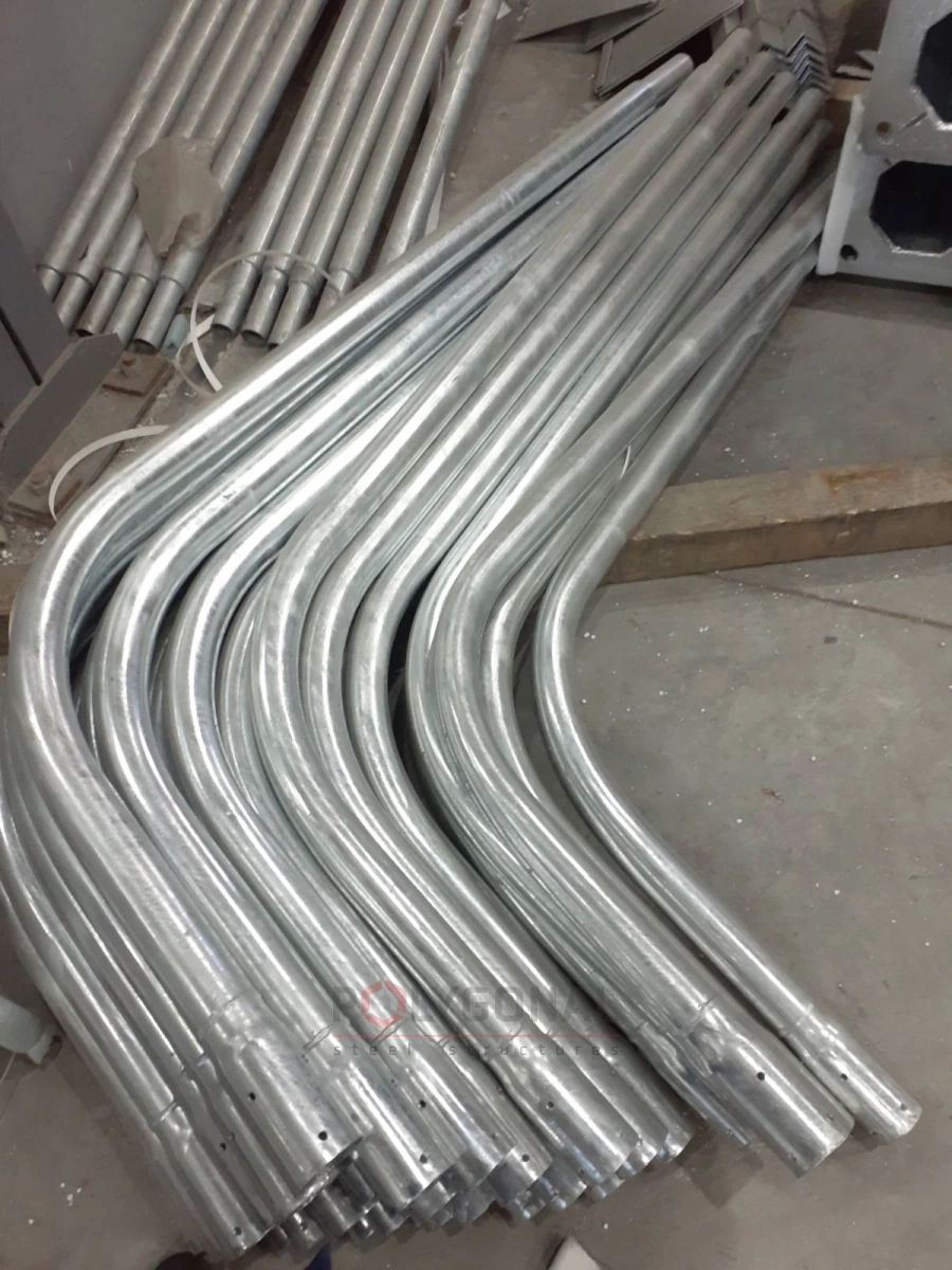
Bracket KO2-1-1-1.5
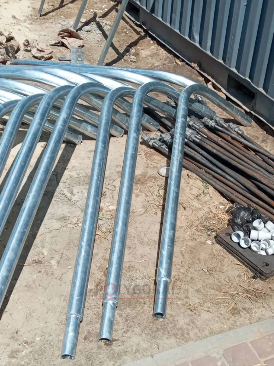
Bracket KO2-2-1-1.5 (120°)
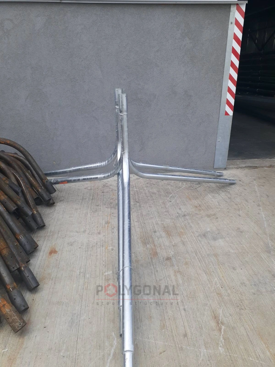
Bracket KO2-3-1-1.5
KP brackets — park type
KP brackets are made for a pole top diameter of 60 mm and have 1 to 3 arms. Types KP1–KP7 differ in shape and in the permitted number of arms. The mark consists of the type, the number of arms and the pole top diameter, for example KP1-2-60.
OG caps and TR crossarms — mounting several floodlights together
When one pole has to carry several floodlights, for example to light a large area, an OG cap or a TR crossarm is used. It is a frame or a bar with mounting points for floodlights. In the mark the type comes first, then the pole top diameter in millimetres, then the fixing method: OG1-60-f, TR1-60-f.
| Mark | Number of floodlights |
|---|---|
| OG1 | 3 |
| OG2 | 4 |
| OG3 | 5 |
| OG4 | 6 |
| OG5 | 8 |
| OG6 | 1 |
| OG7 | 2 |
| OG8 | 2 |
| OG9 | 3 |
| OG10 | 4 |
| TR1 | 1 |
| TR2 | 2 |
| TR3 | 3 |
| TR4 | 4 |
| TR5 | 5 |
| TR6 | 2 |
| TR7 | 3 |
| TR8 | 4 |
| TR9 | 6 |
The exact spacing of the floodlight mounting points on each mark is given in the order drawing; we select the cap or crossarm for the required number and layout of floodlights.
Crossarms
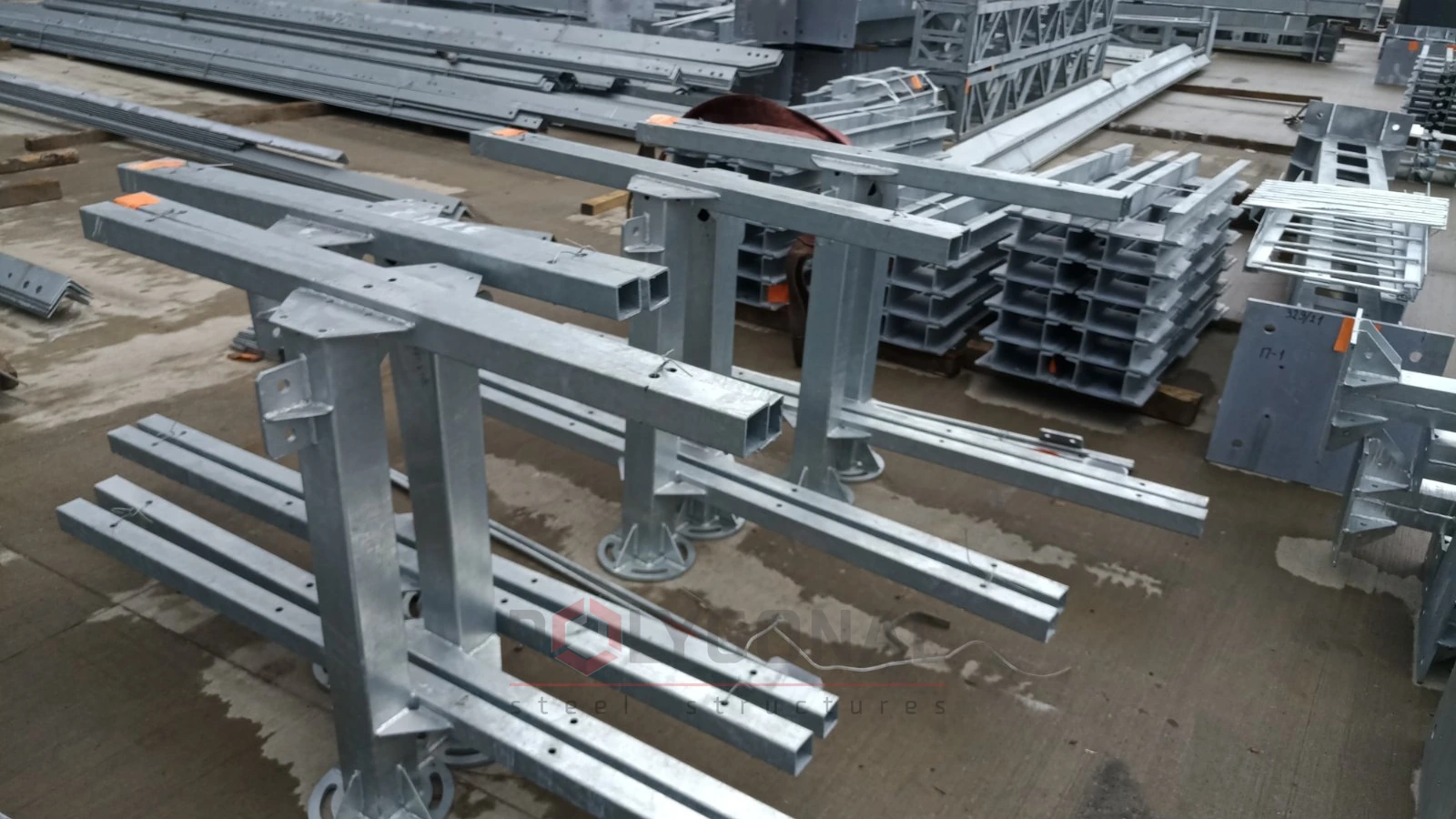
Crossarm TR8-f
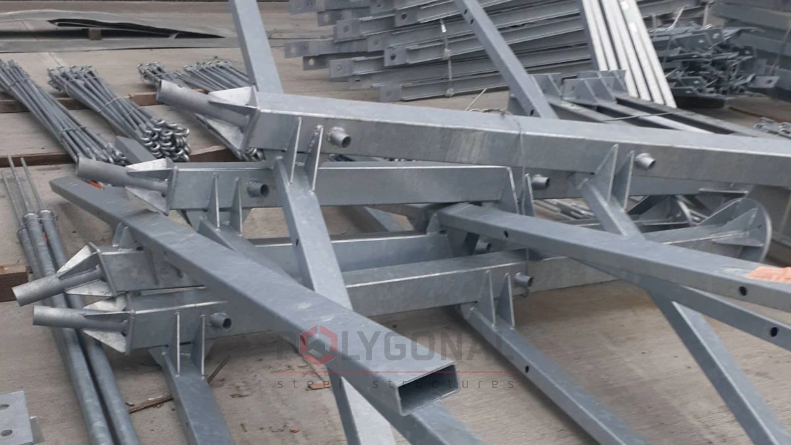
Crossarm TR9-f
Material and coating
Brackets, caps and crossarms are made of S245 steel to DSTU 8539:2015 and hot-dip galvanised to DSTU EN ISO 1461:2024.
How a bracket affects the pole: a UMO-8 example
A bracket carries the luminaire away from the pole axis and lifts it, so the permitted luminaire area gets smaller. You can see this in the load table of UMO poles for an 8 m pole at a wind pressure of 400 Pa. There H is the pole height, Hs the height of the pole with its bracket, and S the reach from the axis. The bracket rows read like this:
- Hs = 9 m for H = 8 m, so the bracket height is 9 − 8 = 1 m and the reach is S = 1.5 m;
- this height and reach match the marks KO1-1-1-1.5 (one arm) and KO1-2-1-1.5 (two arms) in the table above;
- the equipment mass assumed in the table is 15 kg per arm and 50 kg on the pole axis.
| Option | Reach, m | Equipment mass, kg | Permitted area, m² |
|---|---|---|---|
| On the pole axis | — | 50 | 2.396 |
| One-arm bracket | 1.5 | 15 | 1.973 |
| Two-arm bracket | 2 × 1.5 | 2 × 15 | 0.888 |
The base loads are the same in every row: Q = 2.05 kN, M = 12.18 kN·m. Calculation: 1.973 ÷ 2.396 ≈ 0.82, so 18% less; 0.888 ÷ 2.396 ≈ 0.37, so 63% less.
KO3 brackets: two arms of different height
KO3 is asymmetric: the lower arm also has the shorter reach. The mark carries the first value of each pair. In KO3-2-1.1-1, then, the first arm is 1.1 m high with a reach of 1 m, and the second is 0.6 m high with a reach of 0.5 m. Do not mix them up: 1.1 / 0.6 m are the arm heights, while the reaches are 1 / 0.5 m.
| Mark | Arm height, m | Arm reach, m |
|---|---|---|
| KO3-2-1.1-1 | 1.1 / 0.6 | 1 / 0.5 |
| KO3-2-1.2-1.5 | 1.2 / 0.7 | 1.5 / 1 |
| KO3-2-1.4-2 | 1.4 / 0.85 | 2 / 1.5 |
Data from the Structures for Outdoor Lighting catalogue.
Cap or crossarm: which to choose
In the catalogue drawings OG1–OG5 are polygonal frames, from a triangle up to an octagon. The floodlights point in different directions, so the light goes around the pole. A TR crossarm is a straight bar: the floodlights stand in one row (two rows on TR8 and TR9) and light one side. OG6–OG10 are a separate group: cantilever frames for 1–4 floodlights.
When you already know how many floodlights there will be, start from the table:
| Floodlights | OG caps | TR crossarms |
|---|---|---|
| 1 | OG6 | TR1 |
| 2 | OG7, OG8 | TR2, TR6 |
| 3 | OG1, OG9 | TR3, TR7 |
| 4 | OG2, OG10 | TR4, TR8 |
| 5 | OG3 | TR5 |
| 6 | OG4 | TR9 |
| 8 | OG5 | — |
Floodlights on a pole: a check of mass and area
Take a floodlight weighing 20 kg with a windage area of 0.2 m²: these are the upper limits for masts of our PMV range. Three of them on an OG1 cap come to 3 × 20 = 60 kg and 3 × 0.2 = 0.6 m². Eight on an OG5 come to 8 × 20 = 160 kg and 8 × 0.2 = 1.6 m².
Now set this against the UMO-8 table at 400 Pa. The area has a margin: 0.6 m² against 2.396 m² on the axis. The mass does not. The 60 kg exceeds the 50 kg assumed in the table, and even a single floodlight on an arm (20 kg) is heavier than the 15 kg per arm. A pole for a group of floodlights is therefore calculated separately and not taken from the luminaire range.
What to state in a request for a bracket, cap or crossarm
- the mark, or the number of arms or floodlights, and the layout: light around the pole or to one side;
- the diameters per the catalogue (48 mm in the KO table, 60 mm in the KP marks), checked against the pole top and the luminaire seat in its data sheet; for OG and TR the pole top diameter is part of the mark (60 mm in the catalogue examples);
- for OG and TR, the fixing method: “f” or “t”;
- the mass and area of each luminaire or floodlight, from its data sheet;
- the pole series and height, and the wind region;
- the colour, if the zinc is to be painted over.
Bracket reach and pole height
The longer the reach, the larger the bending moment at the base of the pole. The European standard EN 40-2 advises that the bracket reach should not exceed a quarter of the pole height (w ≤ h/4); for the standard itself see Lighting Column Dimensions and Tolerances under EN 40-2. This is a reference recommendation, not a claim that our products conform to the standard.
For the brackets in the tables above the reach of the farthest arm is 1, 1.5 or 2 m. By the quarter rule the lowest pole for each reach is as follows:
| Bracket reach, m | Lowest pole by the rule w ≤ h/4, m |
|---|---|
| 1 | 4 |
| 1.5 | 6 |
| 2 | 8 |
Calculation: h = 4 × w, that is 4 × 1 = 4, 4 × 1.5 = 6, 4 × 2 = 8. This is a guide for a first selection: the pole and bracket pair is confirmed by a calculation of mass, luminaire area and wind region.
UMO poles of different heights: allowable luminaire area
The UMO-8 pole is worked through above. The same load tables give the picture for the other heights in the range: wind pressure 400 Pa, a bracket 1 m high with a reach of 1.5 m. From 6 m upwards, the taller the pole, the smaller the allowable luminaire area: from 3.963 m² on the axis of a 6 m pole to 0.834 m² on a 12 m pole. A two-arm bracket leaves about 37% of the on-axis area on 6 m and 8 m poles, 36% on 10 m and 31% on 12 m.
| UMO pole, m | On the axis, m² | One arm, m² | Two arms, m² |
|---|---|---|---|
| 6 | 3.963 | 3.147 | 1.465 |
| 8 | 2.396 | 1.973 | 0.888 |
| 10 | 1.444 | 1.205 | 0.516 |
| 12 | 0.834 | 0.665 | 0.255 |
Allowable total luminaire area from the load tables of UMO poles: 50 kg is assumed on the axis and 15 kg on an arm. The two-arm share of the on-axis area: 1.465 ÷ 3.963 ≈ 0.37; 0.888 ÷ 2.396 ≈ 0.37; 0.516 ÷ 1.444 ≈ 0.36; 0.255 ÷ 0.834 ≈ 0.31.
Updated:
Brackets, crossarms and caps: frequently asked questions
Which bracket fits my pole?
It depends on the series and on the number of luminaires (arms). Per the catalogue, the KO series has a diameter of 48 mm, while for the KP series 60 mm is the pole top diameter; both are checked against the pole and the luminaire seat. Send us the number of luminaires and the pole top diameter and we will select the right mark.
What is the difference between a cap and a crossarm?
The shape of the frame and the arrangement of the mounting points. The job is the same: holding several floodlights on one pole. Which one to take depends on the number of floodlights and the layout of the lighting installation.
What do the letters “f” and “t” in a mark such as TR1-60-f mean?
The fixing method, that is, how the cap or crossarm is attached to the pole. There are two design variants, and we select the right one for your pole.
Can a two-arm bracket be fitted instead of a one-arm one?
Only after the pole has been checked. In the UMO-8 table the permitted luminaire area is 0.888 m² on a two-arm bracket and 1.973 m² on a one-arm bracket, which is about 2.2 times as much (1.973 ÷ 0.888 ≈ 2.2). That is why the number of arms is agreed with the pole before the order.
How many floodlights can be put on one pole?
The catalogue caps and crossarms are made for 1–8 floodlights. How many the pole itself can carry comes out of a calculation of mass, area and wind region. If you need more, look at a floodlight mast: the masts of our unified PMV range carry up to 16 floodlights.
Is the bracket height included in the pole height?
It depends on what the height is measured to. In the load tables of UMO poles it is not: H is the height of the pole itself, Hs the height of the pole with its bracket (for a UMO-8 with a 1 m bracket, Hs = 8 + 1 = 9 m). EN 40-2, by contrast, measures the nominal height to the luminaire fixing point, and it is that mounting height that is taken into account when choosing the pole height.
What bracket reach can I use on my pole?
EN 40-2 advises no more than a quarter of the pole height: up to 1.5 m for a 6 m pole, up to 2 m for an 8 m pole. The pole and bracket pair is finally checked by a calculation of mass, luminaire area and wind region.
Related products: Brackets, caps and crossarms · Street lighting columns · High-mast lighting
Read also: Installation of Multi-sided Poles and Masts · Solar Street Lighting · Power Line Pole Types by Purpose: Suspension, Tension, Angle, Terminal · Cross-arms for 0.4–10 kV Lines: TM and TN Types, Reading the Designation
Get a quote for your requirements
Send us your requirements — we will calculate the price and lead time.