
Home / Products / CCTV poles / CCTV Poles: Height, Rigidity, Camera Mounting
CCTV poles
CCTV Poles: Height, Rigidity, Camera Mounting
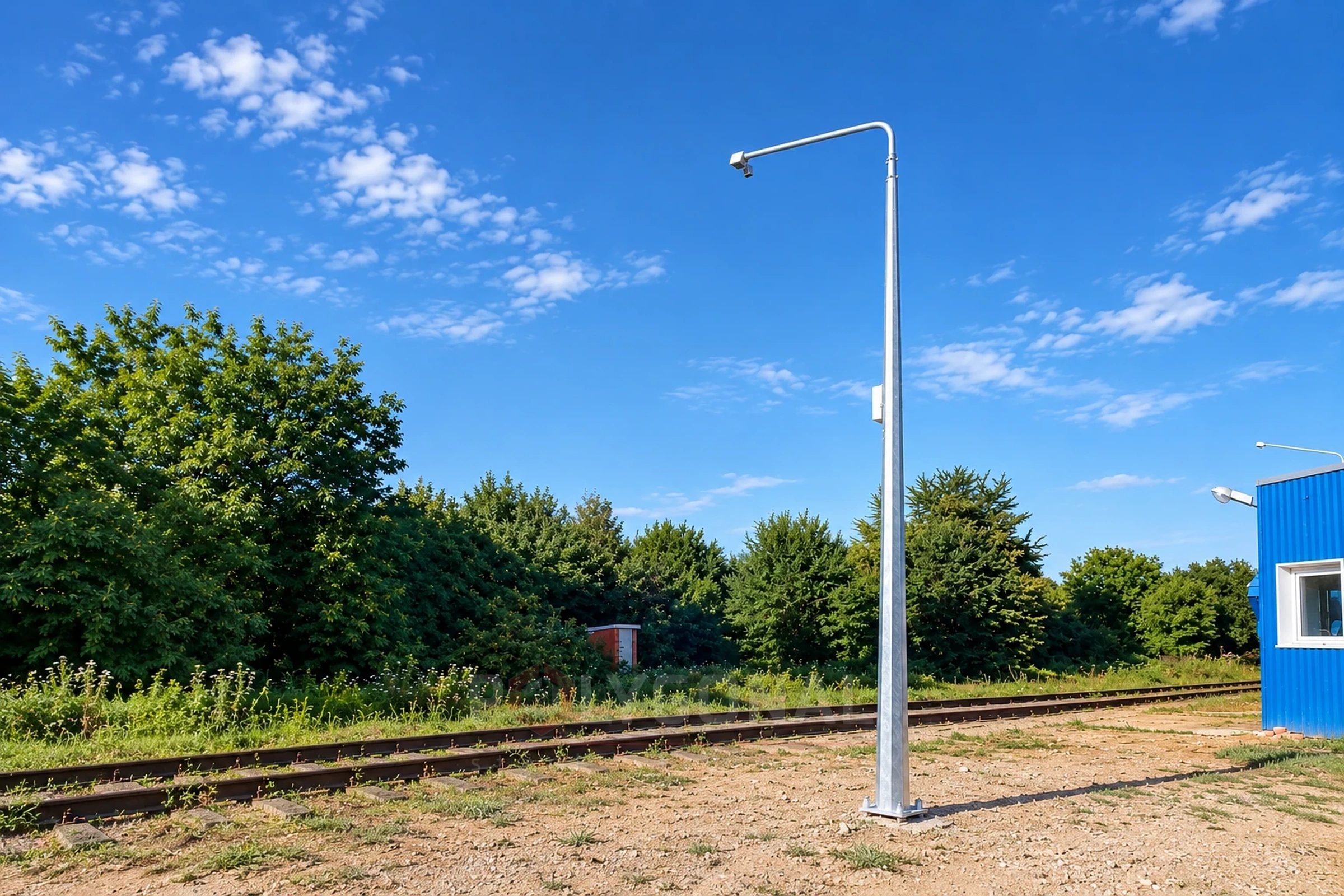
A CCTV camera pole is not just a post: it must keep the field of view stable in the wind, house the cable and equipment, and resist tampering. We explain how to choose the pole’s height, rigidity and fit-out for a camera.
Contents
- Choosing pole height for the field of view
- Rigidity and wind: why a camera image "shakes"
- Brackets, cabinet, cable entry — the fit-out
- Foundation and anchor cage
- Anti-vandal protection
- What to send for a pole selection
- Example: a camera's field of view at mounting heights of 4 m and 6 m
- How sensitive the frame is to tilt: what 1° of sway does
- Why height and bracket reach increase the sway
- What makes a pole stiffer
- A camera and a luminaire on one pole
- Checklist and typical mistakes
Choosing pole height for the field of view
Pole height sets the camera’s field of view: the higher the mounting point, the wider the area in frame, but the level of detail (recognising faces or licence plates) at that distance drops. For recognising faces and plates, a camera is usually mounted lower and closer to the subject; for surveying a large area (a car park, a perimeter) it is mounted higher.
The lens’s angle of view together with the mounting height sets the size of the area in frame and the blind spot directly under the pole. A bracket (see below) offsets the camera from the shaft and reduces that blind spot.
Rigidity and wind: why a camera image “shakes”
A camera mounted on a pole that is too thin or too tall without a rigidity margin sways in the wind — even a small movement of the shaft at the top, where the camera sits, produces noticeable shake in the picture, especially with zoom. The shaft size (diameter and wall thickness) is calculated for the wind region and for the mass and sail area of the camera, housing and bracket, the same way as for any other steel pole (see CCTV Poles).
The taller the pole and the longer the bracket reach, the greater the wind-load moment at the base, so such poles need a larger shaft diameter and a stronger foundation.
Brackets, cabinet, cable entry — the fit-out
- bracket: offsets the camera sideways from the shaft axis to the needed distance and height; its shape and reach are chosen for the specific camera model and task;
- equipment cabinet: mounted on the pole or at its base, housing switching and power equipment (with heating or cooling if needed);
- cable entry: the tubular shaft lets power and signal cable run inside rather than along the outside, protecting it from weather and mechanical damage.
The number and position of the technological cable openings and equipment mounts are agreed at the design stage for the specific pole.
Foundation and anchor cage
The pole is fixed to the foundation through a flange connection with an anchor cage and anchor bolts, or set directly into the ground — the method depends on the site conditions, the pole height and the soil type. Foundation design follows the same principles as for other poles: Lighting Pole Foundations.
Anti-vandal protection
For poles in locations with a higher risk of deliberate damage: routing the cable entry and connections inside the shaft (no external access), a hard-to-reach lock on the base cabinet with reinforced hinges, and a mounting height for the lower access point high enough to make access without special equipment difficult. The specific set of measures is agreed for the site’s requirements.
What to send for a pole selection
The number and mass of cameras, the required field of view and mounting height, the location (wind region), the site type (grounds, road, railway facility) and whether an equipment cabinet is needed. Leave blank whatever you do not know and we will clarify. See also CCTV Poles and related solutions.
Example: a camera’s field of view at mounting heights of 4 m and 6 m
Suppose the camera is tilted 30° below the horizon and its vertical angle of view is 40° (illustrative values). The rays bounding the frame run at 50° and 10° below the horizon, so the strip of ground in frame stretches from h ÷ tan 50° to h ÷ tan 10°, where h is the camera height above the ground, which we take as level and horizontal for this example.
This estimate does not replace the camera’s data sheet: the real angles depend on the lens, the tilt setting and the terrain. It only shows how the mounting height moves the edges of the frame.
| Camera height, m | From, m | To, m |
|---|---|---|
| 4 | 3.4 | 22.7 |
| 6 | 5.0 | 34.0 |
The values use tan 50° ≈ 1.1918 and tan 10° ≈ 0.1763; distances are measured from the camera’s projection on the ground. Raising the camera from 4 to 6 m pushes the far edge out by 11.3 m, but the blind spot grows from 3.4 to 5.0 m.
How sensitive the frame is to tilt: what 1° of sway does
The far edge of the frame in the example is formed by a ray only 10° below the horizon, which is a very shallow angle. So even a small tilt of the camera moves the point where that ray meets the ground a long way. Below is the same example if the pole’s sway tilts the camera 1° further down or 1° further up; the far edge then corresponds to a ray at 11° or 9°.
For a 40° angle of view, one degree is about 1/40 of the frame height, and with zoom the angle of view narrows, so the same degree takes up a larger share of the frame. For a fraction of a degree the shift is proportionally smaller, but it is still noticeable.
| Camera height, m | Far edge, tilted 1° down, m | Far edge, base frame, m | Far edge, tilted 1° up, m |
|---|---|---|---|
| 4 | 20.6 | 22.7 | 25.3 |
| 6 | 30.9 | 34.0 | 37.9 |
The far edge is h ÷ tan 11° (tan 11° ≈ 0.1944) and h ÷ tan 9° (tan 9° ≈ 0.1584). In metres, a 1° tilt shifts it by roughly 2.1–2.6 m at a height of 4 m and by 3.2–3.9 m at 6 m.
Why height and bracket reach increase the sway
A pole with a camera on top can be simplified to a cantilever: the lower end is fixed in the foundation and the wind force on the equipment acts at the upper end. For a constant cross-section with a force at the free end, the deflection of the top grows with the cube of the height and the rotation of the top with its square. It is the rotation of the top that tilts the camera and shifts the frame.
The table compares poles of 4, 6 and 8 m, with the 4 m pole taken as one unit. The cross-section and the force at the top are the same in every row.
| Pole height, m | Moment at the base | Deflection of the top | Rotation of the top |
|---|---|---|---|
| 4 | 1 | 1 | 1 |
| 6 | 1.5 | 3.4 | 2.25 |
| 8 | 2 | 8 | 4 |
This compares trends and is not a calculation: a real pole has a variable cross-section, the wind also acts on the shaft itself, and the wind pressure in the calculation grows with height, which only strengthens the effect. The shaft size is set by an engineer in a full calculation.
What makes a pole stiffer
Rigidity is a requirement of its own, not the same thing as strength: a pole may be nowhere near failing and still sway enough to spoil the picture. These are the things that really change how far the top moves:
- a larger shaft diameter is the strongest lever: for a thin-walled section the stiffness grows roughly with the cube of the diameter, so 20% more diameter makes the shaft about 1.7 times stiffer (the sail area of the shaft itself grows only in proportion to the diameter);
- a thicker wall raises stiffness only in proportion: 20% more thickness makes it just 1.2 times stiffer, so for the same extra metal the diameter does more than the wall;
- a lower mounting point and a shorter bracket reduce both the moment and the rotation of the top;
- the foundation matters too: a yielding foundation or soil tilts the whole pole, and the camera tilts with it (see Lighting Pole Foundations).
A camera and a luminaire on one pole
A combined pole is convenient where lighting is needed anyway: one shaft and one foundation instead of two. But the calculation is then made for the whole set: the mass and sail area of the luminaire and its bracket are added to those of the camera, and each element is counted at its own height.
The camera position is agreed with the luminaires: direct light entering the lens can wash out part of the frame. The pole height for the luminaires is chosen on the same principles as for an ordinary lighting pole (see How to Choose the Height of a Lighting Pole).
Light on the guarded area also affects the quality of the night picture, so at sites with lighting poles it is worth considering both tasks together. See also lighting poles.
Checklist and typical mistakes
- the field of view has been checked by calculation: the area you need does not fall in the blind spot under the camera;
- the height of each camera and the bracket reach are known, not only the pole height;
- the mass and sail area include the camera, housing, bracket, illuminator and cabinet, and the wind pressure W0 is taken from the W0 table for the nearest regional capital;
- the stiffness of the shaft at the camera height has been checked, not only its strength;
- mistake: mounting the camera as high as possible without checking the level of detail;
- mistake: choosing a pole by height alone, without stating the wind region and the site type;
- mistake: adding cameras, radio equipment or a floodlight later to a pole calculated for one camera, without recalculation.
Updated:
CCTV camera poles: frequently asked questions
What pole height should I choose for a CCTV camera?
It depends on the task: for recognising faces and plates the camera is mounted lower and closer to the subject; for surveying a large area, higher. The exact height is chosen together with the lens’s angle of view and the required frame area.
Why does a camera picture “shake” in the wind?
Because the pole lacks rigidity at the camera’s mounting height — a shaft with too small a diameter or wall thickness sways in the wind. The shaft size is calculated for the wind region and the equipment mass to avoid this sway.
Can the cable run inside the pole?
Yes, the tubular shaft lets power and signal cable run inside, protecting it from weather and mechanical damage.
How is the pole fixed to the foundation?
Through a flange onto an anchor cage with anchor bolts, or set into the ground, depending on the site conditions.
What anti-vandal measures are used?
Routing the cable and connections inside the shaft, a reinforced lock on the equipment cabinet, and a mounting height for the access point high enough to hinder tampering.
How many cameras can be fitted on one pole?
A calculation decides this, not a fixed number: each camera adds mass and sail area, and its height and bracket reach set the lever arm of the force. To select a pole we need the number and mass of the cameras, their heights, the reach, the wind region and the cabinet size. A camera can be added after installation only after a recalculation.
Can a camera and a luminaire share one pole?
Yes, their mass and sail area are added together in the calculation, and the camera position is agreed with the luminaires so that their light does not enter the lens.
Can the camera be raised on a pole that is already installed?
Not without a recalculation: as the mounting height grows, so do the moment, the deflection and the rotation of the top, so a different shaft section or foundation may be needed.
How can I estimate whether the area I need will be in frame?
For level ground, the edges of the frame are h ÷ tan of the ray angle below the horizon. Take the angles from the camera’s data sheet; on a slope or uneven ground the edges shift, so the calculation is refined for the specific site.
Related products: CCTV poles · Hot-dip galvanising
Read also: Installation of Multi-sided Poles and Masts · Solar Street Lighting · Power Line Pole Types by Purpose: Suspension, Tension, Angle, Terminal · Cross-arms for 0.4–10 kV Lines: TM and TN Types, Reading the Designation
Get a quote for your requirements
Send us your requirements — we will calculate the price and lead time.