
Home / Services / Technical inspection / Cracks in Structures: Assessment and Repair
Technical inspection
Cracks in Structures: Assessment and Repair
Why cracks appear, how they are classified and measured, and the ways of repairing cracks and strengthening damaged structures.
Contents
Why it matters to find and assess cracks
Timely detection and repair of defects and damage in building structures is a pressing problem: the appearance and growth of cracks show that a structure is in poor condition and can worsen the operating conditions of the building as a whole. Determining the causes and the way cracks develop lets us choose the right repair method and ensure that the structures work reliably. The crack width in reinforced concrete structures is limited according to the type of reinforcement and the operating conditions (for example, for structures indoors the permitted value is about 0.4 mm, for tanks and for structures in the ground and outdoors, 0.1–0.2 mm).
When buildings are accepted into service, cracks of shrinkage, settlement and thermal nature that are visible to the eye may be found in the structures, and these must be measured. Sometimes the settlement of a building and the development of cracks in particular areas must also be monitored so that measures can be taken in time.
Types of cracks
By cause, cracks are divided into:
- settlement cracks: caused by uneven settlement of the base due to shortcomings in design and survey work, in operation or by natural processes; they appear first in the foundation and plinth and then spread up the height of the building; they are located mostly at places of weakened sections, at junctions of walls and floors, and where outer and inner walls join. They can damage utility entries, reduce the overall stiffness of the structure and even cause an accident;
- shrinkage cracks: a result of breaking the manufacturing technology at the factory or on site; a fine, random network of cracks of small width; they harm the reinforcement and cause weathering of the outer layer;
- thermal cracks: caused by thermal expansion or contraction of elements with no expansion joints; the width changes with daily and seasonal temperature swings (cracks open as temperature rises and close as it falls);
- corrosion cracks: appear when the products of reinforcement corrosion build up in the concrete and tensile stresses arise; they usually develop only to the depth of the cover;
- load cracks: arise when a structure is overloaded through mistaken design solutions, factory defects, damage in transport and erection or breach of operating rules; their pattern depends on the deformation (buckling, tearing off, compression, tension, shear); at the bearings of floors on load-bearing walls, cracks, crushing and spalling are possible.
How cracks are monitored and measured
When cracks appear in load-bearing structures, monitoring is organised with tell-tales, the measuring places are marked and drawn on the structure drawings (with the tell-tale positions and dates), and a graph of opening is drawn for each crack. Methods of assessing crack opening are qualitative (they show that cracks exist and how they tend to develop, without instrument measurement) and quantitative (they measure crack width or growth; contact and remote, for one-off and systematic measurements).
The most common qualitative method is a tell-tale of cement mortar, plaster, water glass, paper or photoelastic material: when the crack widens, the tell-tale breaks. The luminescent method (the surface is coated with a luminescent compound, which is then removed and the surface examined in ultraviolet) makes fine cracks visible; the chemical (ammonia acting on light-sensitive paper) and acoustic (tapping, ultrasonic pulses, a flaw detector) methods find through cracks and check the continuity of the structure.
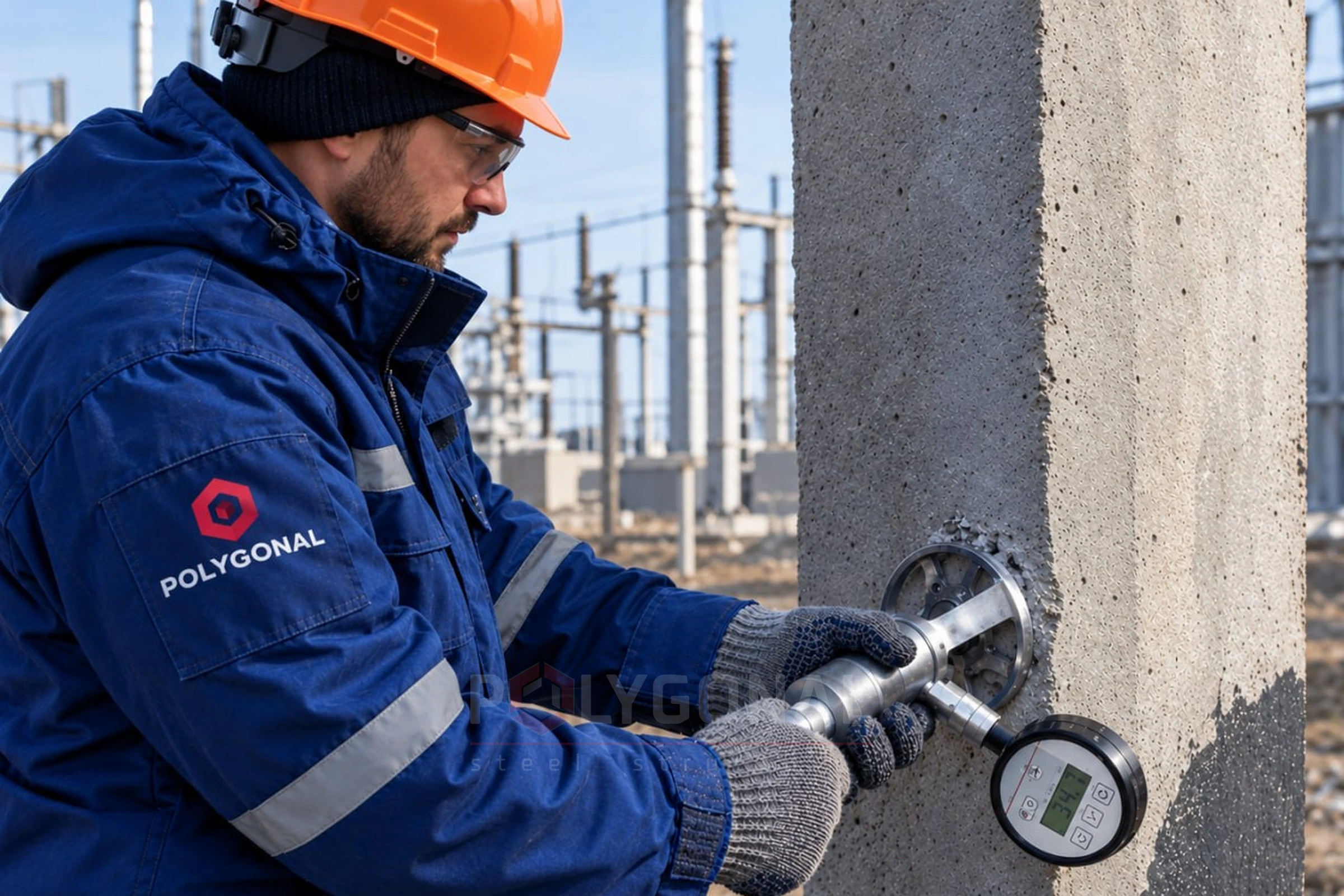
Contact means of measuring crack width include rulers, a tell-tale with divisions, a crack-width gauge (a set of calibrated lines on a transparent plate), a magnifier with a millimetre scale, a microscope, and a dial indicator (accuracy 0.01 mm) for long observations. Optical-mechanical instruments based on a theodolite are used for remote measurement on the facades of tall buildings. Crack length is measured with a curvimeter, ruler or tape, and depth with feeler gauges or from the speed of ultrasonic pulses. It is advisable to make a sketch of the structure showing the cracks, or a photograph with a plate giving the date, place, time and the outdoor and indoor temperature.
Repairing cracks and strengthening structures
The method depends on the cause of the cracks, the type of structure and its condition. The most common approaches are:
- injecting polymer or epoxy compounds into the cracks (low-viscosity fast-setting compounds fill cracks about 0.06 mm wide to a considerable depth); the method can fully restore the damaged structure, although its deformability may be slightly higher;
- fitting reinforced mortar, reinforced concrete or steel closed belts (for brick buildings; a steel belt of 20–36 mm round bar stabilises uneven settlement without complicated underpinning work);
- steel, reinforced concrete and reinforced plaster jackets and sleeves for piers (they raise the load capacity of a pier about 2–2.5 times; the drawbacks are labour and steel consumption);
- building up walls (on one or both sides) with reinforced concrete or reinforced plaster layers, fibre-reinforced concrete or shotcrete, which also protects the walls from climate effects and raises the spatial stiffness of the building;
- unloading structures: wall-side posts to relieve external wall panels, steel beams under floor slabs;
- strengthening floor slabs: increasing the section height (a topping of 20–30 mm), unloading steel beams, prestressed ties and trussed-rod systems;
- strengthening piles with a steel prestressed clamp where the pile heads of pile foundations are failing;
- polymer-mortar reinforced keys (to restore buildings damaged by earthquakes and to raise seismic resistance).
The design for strengthening and repairing load-bearing structures is prepared by a specialist design organisation.
Updated:
Cracks in structures: frequently asked questions
What crack width is allowed?
It depends on the conditions: about 0.4 mm for reinforced concrete structures indoors, 0.1–0.2 mm for tanks and for structures in the ground or outdoors.
What are the main types of cracks?
Settlement, shrinkage, thermal, corrosion and load cracks — each type has its own cause and characteristic development pattern, described above.
How are thin cracks repaired without dismantling the structure?
By injecting low-viscosity polymer or epoxy compounds, which fill cracks about 0.06 mm wide to a considerable depth, fully restoring the damaged structure.
How is uneven settlement of a brick building stabilised?
By fitting a reinforced closed belt, for example a steel one made of 20–36 mm round bar, without complicated underpinning work.
Related products: Technical inspection · Steel structure design (structural and detail drawings)
More on this topic: Technical Inspection of Buildings: Procedure and Passport · Diagnostics of Structural Condition · Building Condition Monitoring: Inspections and Records · Who May Conduct a Technical Inspection of Buildings and Structures · Technical Inspection Cost: What It Depends On · Steel Properties in a Technical Inspection
Get a quote for your requirements
Send us your requirements — we will calculate the price and lead time.